| Page: |
| Home > Technical Chat > 16V K headed turbo, race engine, need for restrictor | ||||||
|
8604 Posts Member #: 573 Formerly Axel Podland |
30th Sep, 2010 at 09:18:51pm
The onset of failure of the compressor due to insufficient inlet pressure will feel like a stone wall.
Saul Bellow - "A great deal of intelligence can be invested in ignorance when the need for illusion is deep."
|
|||||
 1137 Posts Member #: 1450 Post Whore Near Paris - France |
1st Oct, 2010 at 05:15:18pm
But to what extent ?
Rusty by nature
On 23rd Jun, 2008 paul wiginton said:
They said "That sounds rough mate." I said "Cheers it cost me a fortune to make it sound like that!" |
|||||
 6754 Posts Member #: 828 Post Whore uranus |
1st Oct, 2010 at 05:51:12pm
addy ,having the restrictor after the turbo ,eg r5,makes a totally different set of rules come into play. Medusa + injection = too much torque for the dyno ..https://youtu.be/qg5o0_tJxYM |
|||||
|
1137 Posts Member #: 1450 Post Whore Near Paris - France |
1st Oct, 2010 at 07:08:52pm
Sorry, I understood "close to the inlet" the wrong way ... Rusty by nature
On 23rd Jun, 2008 paul wiginton said:
They said "That sounds rough mate." I said "Cheers it cost me a fortune to make it sound like that!" |
|||||
 1849 Posts Member #: 672 The oversills police Oslo, Norway |
19th Aug, 2011 at 09:58:28am
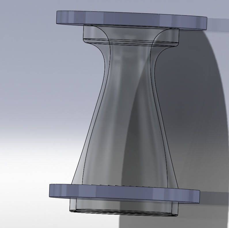
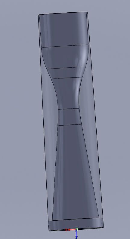
I will ramble on a bit here, as I am midway designing the restrictor.
|
|||||
|
1849 Posts Member #: 672 The oversills police Oslo, Norway |
19th Aug, 2011 at 10:00:35am
also, do you think that the floXpress in Solidworks would have any meaningful usage in this exercise? I have tried (as you can probably see from the lids)... |
|||||
|
8604 Posts Member #: 573 Formerly Axel Podland |
19th Aug, 2011 at 10:33:13am
I did some work trying to analyise maximum compressor air flow based on the inducer diameter here:
Saul Bellow - "A great deal of intelligence can be invested in ignorance when the need for illusion is deep."
|
|||||
|
1849 Posts Member #: 672 The oversills police Oslo, Norway |
19th Aug, 2011 at 11:26:47am
The venturi profile is purely based on readin some info around and drawing in Solidworks. I have had troubles finding anything scientific about optimum profiles.
|
|||||
|
8604 Posts Member #: 573 Formerly Axel Podland |
19th Aug, 2011 at 11:35:37am
As the absolute pressure at the compressor inlet drops towards zero, there is a point where it will start to deliver less flow than shown on the compressor map due to separation (vacuum pockets) in the inlet stream.
Saul Bellow - "A great deal of intelligence can be invested in ignorance when the need for illusion is deep."
|
|||||
|
1849 Posts Member #: 672 The oversills police Oslo, Norway |
19th Aug, 2011 at 12:00:42pm
On 19th Aug, 2011 Paul S said:
As the absolute pressure at the compressor inlet drops towards zero, there is a point where it will start to deliver less flow than shown on the compressor map due to separation (vacuum pockets) in the inlet stream. This will depend very much on the inlet design of the compressor wheel and the speed of rotation. So, it is pretty much an example of try it and see what happens then :) The WRC cars run higher CR than me on a 2 liter engine with a much less ideal restrictor, and make around 300-340 hp. One can also see from the drawing on page 1 that the Toyota cheaters had a 50 mm inducer. |
|||||
|
Site Admin  15302 Posts Member #: 337 Fearless Tom Fenton, Avon Park 2007 & 2008 class D winner & TM legend. |
19th Aug, 2011 at 12:13:55pm
I've only skim read so forgive me if this has been mentioned, but the WRC cars due to the restrictor are tuned for massive torque. They "only" make 300bhp but they do so at relatively low revs, so make huge torque. They make use of this with the 7 speed boxes, you only have to hear one flying through the forests pulling gear after gear using the torque to work out how they are fast and still have the restrictor.
On 29th Nov, 2016 madmk1 said:
On 28th Nov, 2016 Rob Gavin said:
I refuse to pay for anything else Like fuel 😂😂 |
|||||
|
1849 Posts Member #: 672 The oversills police Oslo, Norway |
19th Aug, 2011 at 12:19:54pm
I know Tom. They wont make any more HP after around 5000 rpm. but this is in a 2 litre engine. I am only using a 1.343 liter engine. |
|||||
|
8604 Posts Member #: 573 Formerly Axel Podland |
19th Aug, 2011 at 12:35:41pm
Just get some long intake runners on it Andre. Saul Bellow - "A great deal of intelligence can be invested in ignorance when the need for illusion is deep."
|
|||||
|
1849 Posts Member #: 672 The oversills police Oslo, Norway |
19th Aug, 2011 at 12:50:36pm
:) the intake runners from the o ring face will approximately be 180 mm. and then there is some centimeters from the end of the trumpet to the wall in the plenum |
|||||
|
1849 Posts Member #: 672 The oversills police Oslo, Norway |
19th Aug, 2011 at 01:13:12pm
this is a close to optimum restrictor according to the following source: http://nepis.epa.gov/Exe/ZyNET.exe/500013Z...s=10&ZyEntry=13
|
|||||
|
8604 Posts Member #: 573 Formerly Axel Podland |
19th Aug, 2011 at 01:36:31pm
My understanding is that if you limit the angle of the tapers to 10 degrees (5 degrees each side), then the pressure loss is minimised.
Saul Bellow - "A great deal of intelligence can be invested in ignorance when the need for illusion is deep."
|
|||||
|
1849 Posts Member #: 672 The oversills police Oslo, Norway |
19th Aug, 2011 at 01:39:59pm
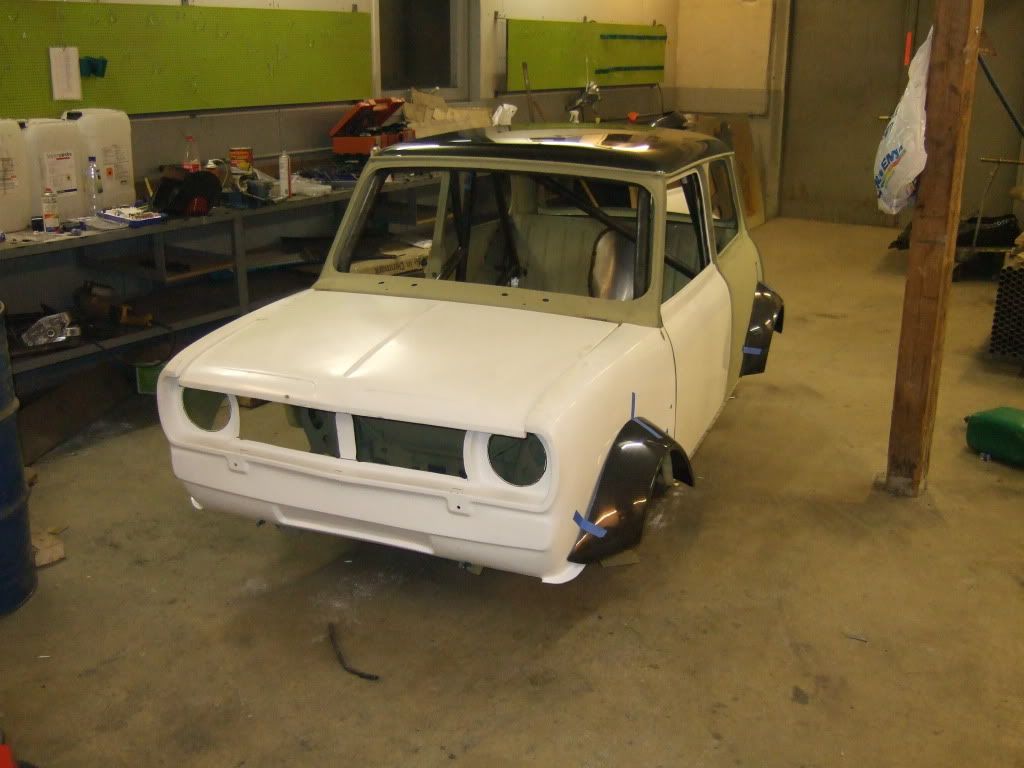
thats on a 5 port right Paul? This is a Bmw 16valve head. 280 mm would be well outside the grille even on a Clubbie like mine... |
|||||
|
8604 Posts Member #: 573 Formerly Axel Podland |
19th Aug, 2011 at 01:43:25pm
That's on a 7 or 8 port.
Edited by Paul S on 19th Aug, 2011. Saul Bellow - "A great deal of intelligence can be invested in ignorance when the need for illusion is deep."
|
|||||
|
1849 Posts Member #: 672 The oversills police Oslo, Norway |
19th Aug, 2011 at 01:54:19pm
I guess this also depends on cams, cam timing, valve sizes and other things like that though? |
|||||
|
8604 Posts Member #: 573 Formerly Axel Podland |
19th Aug, 2011 at 01:56:41pm
Yes, everything needs to be working in harmony.
Saul Bellow - "A great deal of intelligence can be invested in ignorance when the need for illusion is deep."
|
|||||
|
1849 Posts Member #: 672 The oversills police Oslo, Norway |
19th Aug, 2011 at 02:18:51pm
I am using the SC sprint cams. One of the reasons we get away with 12:1 cr |
|||||
|
8604 Posts Member #: 573 Formerly Axel Podland |
19th Aug, 2011 at 03:05:09pm
In that case, use the revs and limit the boost to what can be efficiently delivered by the turbo and restrictor. Saul Bellow - "A great deal of intelligence can be invested in ignorance when the need for illusion is deep."
|
|||||
|
1849 Posts Member #: 672 The oversills police Oslo, Norway |
19th Aug, 2011 at 09:38:59pm
Thats the plan! We are planning to keep the powerband where it is, just raising it. The restrictor should not be to much of a hinderance according to the guy I have seeked help with for this build. I thrust him, but gind it rewarding to figure it out myself as well.
|
|||||
| Home > Technical Chat > 16V K headed turbo, race engine, need for restrictor | ||||||
| ||||||