
| Page: |
| Home > Help Needed / General Tech Chat > mety turbo boost ecu wiring? | |||||||
 1497 Posts Member #: 100 Parisien Turbo Expert Paris\' suburb |
18th Sep, 2008 at 05:06:09pm
as title,
|
||||||
|
1497 Posts Member #: 100 Parisien Turbo Expert Paris\' suburb |
27th Sep, 2008 at 04:39:23pm
?
|
||||||
 10023 Posts Member #: 1456 Mongo Barnsley, South Flatcapshire |
27th Sep, 2008 at 04:47:01pm
i think it needs an rpm signal too.
If something is worth doing, it's worth doing half of. |
||||||
|
1497 Posts Member #: 100 Parisien Turbo Expert Paris\' suburb |
27th Sep, 2008 at 04:52:20pm
yes , that's the b/w that goes to coil?
|
||||||
|
806 Posts Member #: 989 Post Whore North Yorkshire |
27th Sep, 2008 at 05:01:03pm
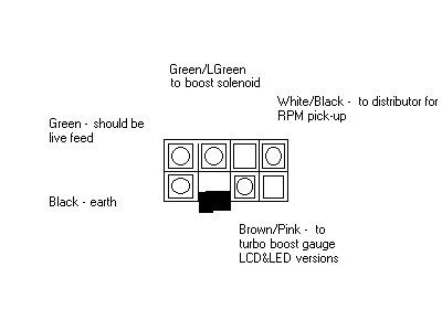
This is the diagram for the molex plug, which should help.
|
||||||
|
1497 Posts Member #: 100 Parisien Turbo Expert Paris\' suburb |
27th Sep, 2008 at 05:10:12pm
thanks,
|
||||||
|
8604 Posts Member #: 573 Formerly Axel Podland |
27th Sep, 2008 at 05:20:59pm
I believe that it senses RPM and closes the solenoid below 4000 rpm.
Edited by Paul S on 27th Sep, 2008. Saul Bellow - "A great deal of intelligence can be invested in ignorance when the need for illusion is deep."
|
||||||
|
1497 Posts Member #: 100 Parisien Turbo Expert Paris\' suburb |
27th Sep, 2008 at 06:57:31pm
Paul, it does also sens boost,
|
||||||
|
806 Posts Member #: 989 Post Whore North Yorkshire |
27th Sep, 2008 at 07:54:21pm
It senses RPM and boost (boost pressure in the plenum, NOT manifold pressure!). Above about 4000rpm it starts to modulate the solenoid open and closed, which bleeds air from the wastegate (the boost solenoid is always closed except when modulating). The boost will rise steadily to 7psi at about 6200rpm, it doesn't change in one go from 4 psi to 7 psi.
"MetroTurbo" said:
The Metro Turbo boost modulation system is a simple, yet sophisticated (for the early eighties, anyway!), means of controlling the boost pressure of the turbocharger and it’s operation is often misunderstood. What does it do – well, quite simply, it increases boost from the set wastegate actuator pressure of 4 psi, up to 7 psi. This is done gradually from 4500rpm to 6000rpm. Why design and install extra equipment to increase the boost to 7 psi, when a different wastegate actuator could be fitted so that the turbo always produces 7 psi? This is what the BL design engineers wanted to do, and if it had have been done the Metro Turbo would have had blistering performance. The good old A Series engine was more than capable of coping with the demands that 7 psi of boost would put upon it. The problem was the gearbox. With boost levels of 7 psi, the reliability of the gearbox dropped below that which is expected of a production car. One aspect of a turbocharged engine is that they have a tendency to produce massive mid range torque figures, and the Metro was no exception. It was this mid range torque that was causing the gearbox problem. The boffins at BL determined that to maintain long term reliability, the gearbox could cope with no more 95ft lb of engine torque. Just to be on the safe side, it was decided that the engine would produce no more than 85ft lb. With the boost at 7 psi, well over 95ft lb of torque was produced between about 4000 and 4500rpm. The idea of the boost modulator was to limit the mid range torque. This is represented in the graphs below. 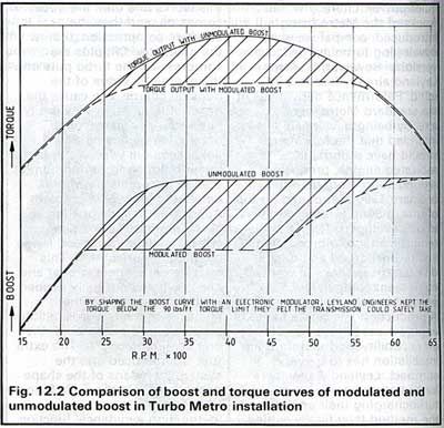
So, how is this done? The wastegate is set at approximately 4 psi. Without the modulator, the boost would never rise above 4 psi and the performance of the car would be noticeably less. The wastegate senses when to open by a pipe that is connected to the turbocharger housing (on the outlet of the compressor), to the wastegate actuator diaphragm. It is the turbo outlet pressure that operates the actuator, and opens the wastegate. Also connected to the pipe to the wastegate actuator is the boost solenoid valve. The boost solenoid valve is part of the boost modulating system, and is directly connected to the ECU. We shall come back to it in a moment. These components can be seen on the diagram below. 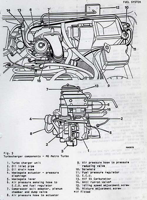
The ECU is an electronic device that measures engine RPM, and the boost level in the plenum chamber, and then operates the boost solenoid as required (it also operates the LED or LCD boost gauge, where fitted). At about 3300rpm, the boost has reached approx 4psi, and the wastegate begins to open. Once the engine rpm has reached 4500rpm, it has passed the point at which it will produce excessive torque if the boost were 7 psi, so the boost modulation comes in to play. The modulator starts to fool the wastegate into thinking the boost level is dropping, so the wastegate starts to close. This is done by rapidly opening and closing the boost solenoid mentioned earlier, which bleeds some of the signal air from the wastegate allowing it to start closing, and the boost begins to rise. The boost level steadily rises with the engine rpm until there is approx 7psi of boost at about 6000rpm. 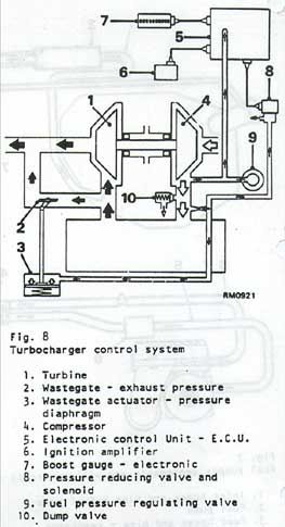 |
||||||
|
1497 Posts Member #: 100 Parisien Turbo Expert Paris\' suburb |
27th Sep, 2008 at 08:17:04pm
it does see plenum pressure in genuine form, in my form it does see manifold one (because it is reduced regarding plenum one).
|
||||||
|
806 Posts Member #: 989 Post Whore North Yorkshire |
27th Sep, 2008 at 08:59:28pm
The ecu is normally bomb proof, but it could be knackered. A digital voltmeter might not pick up the voltage changes from the green wire, as it may be too quick for it read, but as you have proved the solenoid works there is only the ecu left. |
||||||
|
1497 Posts Member #: 100 Parisien Turbo Expert Paris\' suburb |
28th Sep, 2008 at 06:15:42am
I'll test another one as soon as I put my hands on.
|
||||||
|
2498 Posts Member #: 1954 Post Whore Luton Bedfordshire |
28th Sep, 2008 at 10:39:19am
That explains why mine only produces 3psi, thought the ECU's were bomb proof. I thought that the Metro turbos were limited to 3psi but could be run at 7-10psi at your own cost.
Own the day
|
||||||
| Home > Help Needed / General Tech Chat > mety turbo boost ecu wiring? | |||||||
|
|||||||
| Page: |