
| Page: |
| Home > Beginners Tech > Turbo Plumbing, actuator, pipe work, dump valve, bleed valve | |||||||
 3329 Posts Member #: 184 Senior Member Melton Mowbray, Pie Country |
28th Nov, 2008 at 08:14:19am
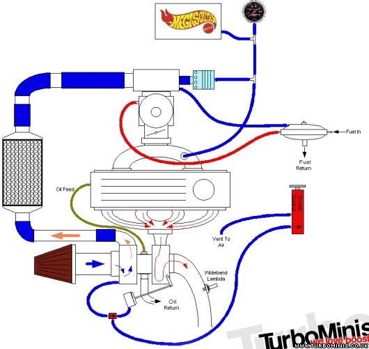
I have recently been helping a chum build a Imp Turbo engine and he asked me if I could sketch out the basics of the turbo plumbing, so I did and I liked them so much I though I would share them.
Edited by Ben H on 19th Aug, 2012. http://www.twin-turbo.co.uk
|
||||||
|
8604 Posts Member #: 573 Formerly Axel Podland |
28th Nov, 2008 at 08:33:33am
Good diagrams.
Saul Bellow - "A great deal of intelligence can be invested in ignorance when the need for illusion is deep."
|
||||||
|
3329 Posts Member #: 184 Senior Member Melton Mowbray, Pie Country |
28th Nov, 2008 at 08:40:33am
That was one area I was debating if I should have the regulator or not. There are various different ways of doing it, and I doubt that a rising rate regulator is used often. The fact that I have shown the fuel rail as a dead end should give you a clue of how it is working there. Your description is perhaps more conventional though. http://www.twin-turbo.co.uk
|
||||||
|
3004 Posts Member #: 2500 Post Whore Buckinghamshire |
28th Nov, 2008 at 09:38:25am
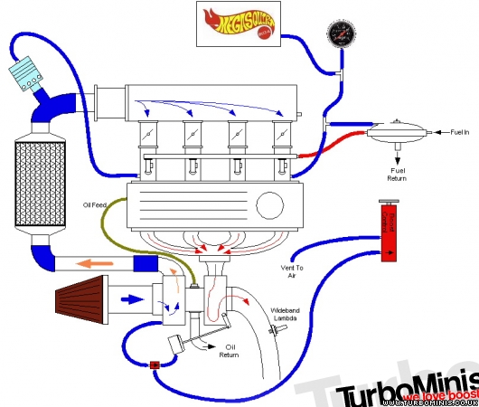
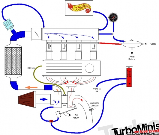
Informative.You show,on the last diagram,the dump valve between the I/C and the plenum,which is the way I have done it, purely as a matter of convenience -space considerations. In a recent thread Rod S suggested I should put it before the intercooler and,whilst I respect his opinion and greater experience, I dont see what difference its likely to make.
|
||||||
 4559 Posts Member #: 786 Post Whore Bermingum |
28th Nov, 2008 at 10:41:46am
Hi
VEMs Authorised Installer / Re-seller. K head kits now available!
|
||||||
 (2)[/url] by [url=https://www.flickr.com/photos/150672766@N03/]Rod Sugden[/url], on Fli) 5988 Posts Member #: 2024 Formally Retired Rural Suffolk |
28th Nov, 2008 at 11:50:54am
As Gavin says, OEM seem to fit them "hot side" (it certainly is on my daily and is still the original at 120k miles so the materials must generally be OK for the temperatures), but remember, I made my suggestion when you were changing to a recirculating valve - Ben's diagrams are for atmospheric valves.
Schrödinger's cat - so which one am I ??? |
||||||
|
3004 Posts Member #: 2500 Post Whore Buckinghamshire |
28th Nov, 2008 at 03:07:23pm
Obliged again for the explanation. As I said, I used the cold side merely because it was convenient and happily it is also the shortest recirculating path. Looks like I might have got one thing right this time ! Onward and upward. |
||||||
|
4314 Posts Member #: 700 Formerly British Open Classic The West Country |
28th Nov, 2008 at 04:17:00pm
Nice drawings.
Isambard Kingdom Brunel said:
Nothing is impossible if you are an Engineer |
||||||
|
3329 Posts Member #: 184 Senior Member Melton Mowbray, Pie Country |
28th Nov, 2008 at 05:34:21pm
On 28th Nov, 2008 Rob H said:
Nice drawings. I'm not a fan of all the Tee Pieces for the boost gauge, regulator and ECU, personally I'd use individual pipe for each of them but that's me. I do agree with you there, but for convenience I have done it like that on the drawing. It just depends on how many holes you want to make. http://www.twin-turbo.co.uk
|
||||||
|
4314 Posts Member #: 700 Formerly British Open Classic The West Country |
28th Nov, 2008 at 05:43:31pm
Remember holes weigh less than tee pieces. LOL. Isambard Kingdom Brunel said:
Nothing is impossible if you are an Engineer |
||||||
 3692 Posts Member #: 1833 Formally mini_majic Auckland, New Zealand |
28th Nov, 2008 at 05:55:49pm
one thing for the individual throttle bodies one, shouldn't the vacuum line be linked over all 4 bodies?
|
||||||
 8297 Posts Member #: 408 Turbo Love Palace Fool Aylesbury |
28th Nov, 2008 at 06:43:14pm
On 28th Nov, 2008 Paul S said:
Good diagrams. However, the fuel regulator works differently on the injection setups. Fuel goes in one end of the fuel rail and then the regulator sits the other end, controlling pressure by returning what is not used. I tend to agree with Paul about the FPR setup on an EFI engine. 
https://www.facebook.com/pages/Fusion-Fabri..._homepage_panel
|
||||||
|
3329 Posts Member #: 184 Senior Member Melton Mowbray, Pie Country |
30th Nov, 2008 at 04:43:54pm
On 28th Nov, 2008 James_H said:
one thing for the individual throttle bodies one, shouldn't the vacuum line be linked over all 4 bodies? sort of 4 into one jobbie to give a decen vacuum reading rather than just the weak one from one cylinder? or am i talking shit? Yes and no. On an NA car with a wild cam it is difficult to get MAP signals so it helps to link them. On a turbo car with a mild cam it is not so bad. Again no hard and fast rules her, just a quick reference to new people. http://www.twin-turbo.co.uk
|
||||||
|
3692 Posts Member #: 1833 Formally mini_majic Auckland, New Zealand |
30th Nov, 2008 at 04:49:45pm
thats cool. diagrams are great and now there is also lots of info below them on different set-ups/options!
|
||||||
|
3329 Posts Member #: 184 Senior Member Melton Mowbray, Pie Country |
17th Mar, 2010 at 08:19:30am
Just changed the title to help the search. http://www.twin-turbo.co.uk
|
||||||
 9502 Posts Member #: 1023 Post Whore Doncaster, South Yorkshire |
17th Mar, 2010 at 09:39:46am
it could be added to Rob's index tread maybe make it easier to find
Yes i moved to the darkside |
||||||
|
3329 Posts Member #: 184 Senior Member Melton Mowbray, Pie Country |
17th Mar, 2010 at 10:42:30am
A good idea, Rob can you sort it? http://www.twin-turbo.co.uk
|
||||||
|
545 Posts Member #: 2928 Post Whore peterborough |
18th Mar, 2010 at 06:08:51pm
awesome thats cleared thinks up for me Jack Jones |
||||||
|
21 Posts Member #: 5544 Member |
21st Mar, 2010 at 09:53:36pm
on the throttle bodied diagrams the boost gauge is T'd into the line from plenumn to regulator but on the carb it's taken from the inlet manifold. is it like that for a reason or can i just T it in? thanks |
||||||
|
289 Posts Member #: 8160 Senior Member , mitcham, surrey, london, cr4 |
1st Apr, 2010 at 07:42:45pm
i have couple questions, sorry if they are silly Nothing special! |
||||||
|
3329 Posts Member #: 184 Senior Member Melton Mowbray, Pie Country |
1st Apr, 2010 at 09:24:35pm
Sparkle,
http://www.twin-turbo.co.uk
|
||||||
 12307 Posts Member #: 565 Carlos Fandango Burnham-on-Crouch, Essex |
1st Apr, 2010 at 09:26:43pm
In your case rather than the megasquirt you will probably be running to the distributor. On 28th Aug, 2011 Kean said:
At the risk of being sigged... Joe, do you have a photo of your tool? http://www.turbominis.co.uk/forums/index.p...9064&lastpost=1 https://joe1977.imgbb.com/ |
||||||
|
289 Posts Member #: 8160 Senior Member , mitcham, surrey, london, cr4 |
1st Apr, 2010 at 09:31:57pm
ok, Thank you :)
Edited by chominsh on 1st Apr, 2010. Nothing special! |
||||||
|
12307 Posts Member #: 565 Carlos Fandango Burnham-on-Crouch, Essex |
1st Apr, 2010 at 09:42:09pm
there is a vacum advance (boost retard?) can on the side of the distributor, but it is probably connected to the manifold already.
On 28th Aug, 2011 Kean said:
At the risk of being sigged... Joe, do you have a photo of your tool? http://www.turbominis.co.uk/forums/index.p...9064&lastpost=1 https://joe1977.imgbb.com/ |
||||||
|
289 Posts Member #: 8160 Senior Member , mitcham, surrey, london, cr4 |
1st Apr, 2010 at 10:09:06pm
On 1st Apr, 2010 mini13 said:
there is a vacum advance (boost retard?) can on the side of the distributor, but it is probably connected to the manifold already. Nothing special! |
||||||
| Home > Beginners Tech > Turbo Plumbing, actuator, pipe work, dump valve, bleed valve | |||||||
|
|||||||


| Page: |