
| Page: |
| Home > MS Code Discussions > Cam-aware siamese code, now with full sequential staged injection | |||||||
|
1267 Posts Member #: 831 Post Whore Montreal, Canada |
15th Feb, 2009 at 08:40:32pm
At last, I have a first version of the siamese code which can take advantage of a cam sensor and adjust the pulse width and injection timing of the inner cylinders. I still haven't added the 2 extra injector drivers so staged injection is not an option for full sequential yet. But that shouldn't take too long to include now that the rest is there but I'm getting extremely close to filling up the CPU memory with the new code so that may become an issue.
Edited by jbelanger on 21st Feb, 2009. |
||||||
|
8604 Posts Member #: 573 Formerly Axel Podland |
15th Feb, 2009 at 09:15:53pm
Excerrrlent.
Saul Bellow - "A great deal of intelligence can be invested in ignorance when the need for illusion is deep."
|
||||||
|
1267 Posts Member #: 831 Post Whore Montreal, Canada |
15th Feb, 2009 at 09:30:40pm
I look forward to see your results.
|
||||||
|
857 Posts Member #: 1778 Post Whore Northants |
15th Feb, 2009 at 09:32:02pm
On 15th Feb, 2009 Paul S said:
I'm off to Paris again next week, but I can play with it when I get back. Don't worry i'll test it for you 
Suppose i better start putting this jimstim together aswell 
Edited by sturgeo on 15th Feb, 2009. |
||||||
|
8604 Posts Member #: 573 Formerly Axel Podland |
15th Feb, 2009 at 10:37:05pm
You leave the car at the back of the barn till I get back.
Saul Bellow - "A great deal of intelligence can be invested in ignorance when the need for illusion is deep."
|
||||||
|
1267 Posts Member #: 831 Post Whore Montreal, Canada |
15th Feb, 2009 at 11:05:28pm
Yes you need the cam sensor on JS10.
|
||||||
 12307 Posts Member #: 565 Carlos Fandango Burnham-on-Crouch, Essex |
15th Feb, 2009 at 11:10:45pm
if you want i can post my built jim stim up. On 28th Aug, 2011 Kean said:
At the risk of being sigged... Joe, do you have a photo of your tool? http://www.turbominis.co.uk/forums/index.p...9064&lastpost=1 https://joe1977.imgbb.com/ |
||||||
 (2)[/url] by [url=https://www.flickr.com/photos/150672766@N03/]Rod Sugden[/url], on Fli) 5988 Posts Member #: 2024 Formally Retired Rural Suffolk |
16th Feb, 2009 at 12:33:23pm
Excellent Jean,
Schrödinger's cat - so which one am I ??? |
||||||
|
1267 Posts Member #: 831 Post Whore Montreal, Canada |
16th Feb, 2009 at 04:56:48pm
Yes the JimStim has the cam signal as well as the crank signal. The phasing of the 2 may not be the same as what you have on your engine but that doesn't make a real difference in the case of a 36-1 since the code only uses the cam sensor to reset the tooth count on the following missing tooth.
|
||||||
|
1267 Posts Member #: 831 Post Whore Montreal, Canada |
16th Feb, 2009 at 05:01:45pm
One more thing about the mechanical setup. It's going to be much tougher to simulate a cam signal since you're going to need some sort of gearing to get the half speed signal unless you use a 72-2 wheel for the first sensor and a separate tooth for the second sensor. The advantage of this is that you get a speed doubling effect and the motor doesn't have to turn as fast to simulate high revs.
|
||||||
|
5988 Posts Member #: 2024 Formally Retired Rural Suffolk |
16th Feb, 2009 at 05:06:08pm
Thanks Jean....
Schrödinger's cat - so which one am I ??? |
||||||
|
8604 Posts Member #: 573 Formerly Axel Podland |
16th Feb, 2009 at 05:07:34pm
Well, I bought the Jimstim in kit form a couple of months ago in readiness for this. Sturgeo is going to build it up this week.
Saul Bellow - "A great deal of intelligence can be invested in ignorance when the need for illusion is deep."
|
||||||
|
1267 Posts Member #: 831 Post Whore Montreal, Canada |
16th Feb, 2009 at 05:27:50pm
For the 36-1 wheel, the phasing is much less critical. The only thing you want is the have the cam tooth away from the crank missing tooth. Something like 30 to 90 degrees before the missing tooth will work fine.
|
||||||
|
5988 Posts Member #: 2024 Formally Retired Rural Suffolk |
16th Feb, 2009 at 05:44:16pm
On 16th Feb, 2009 jbelanger said:
One more thing about the mechanical setup. It's going to be much tougher to simulate a cam signal since you're going to need some sort of gearing to get the half speed signal unless you use a 72-2 wheel for the first sensor and a separate tooth for the second sensor. The advantage of this is that you get a speed doubling effect and the motor doesn't have to turn as fast to simulate high revs. Jean Understood.... being a mechanical engineer at heart, it was my first thought..... the gearing for the 1/2 speed cam sensor would just be hassle, but easily do-able. Now that I know your JimStim can do cam as well, I may just order the kit..... I'm a long way behind Paul,..... or I may twist Joe's arm (mini13) to borrow his..... or I may resort to my second hobby (electronics) and build a suitably divided square wave generator...... On 16th Feb, 2009 jbelanger said:
As for my work, I'm glad it's appreciated and glad to see people involved in this. And I'll have to take a trip to the UK and get a ride in one or all of the siamese code running Minis especially once they have their turbo running. Jean No problem at all, although you might find locating my little bit of the UK quite difficult.... But from my rate of progress, I think you will be visiting Paul first :) Or maybe we both might be running at one of the 09 shows.... (tall order for me  ) )
Schrödinger's cat - so which one am I ??? |
||||||
|
12307 Posts Member #: 565 Carlos Fandango Burnham-on-Crouch, Essex |
16th Feb, 2009 at 06:25:11pm
Yep, can borrow mine no probs Rod,
On 28th Aug, 2011 Kean said:
At the risk of being sigged... Joe, do you have a photo of your tool? http://www.turbominis.co.uk/forums/index.p...9064&lastpost=1 https://joe1977.imgbb.com/ |
||||||
|
5988 Posts Member #: 2024 Formally Retired Rural Suffolk |
16th Feb, 2009 at 06:51:13pm
Cheers Joe,
Schrödinger's cat - so which one am I ??? |
||||||
|
1267 Posts Member #: 831 Post Whore Montreal, Canada |
16th Feb, 2009 at 10:35:06pm
I just realised something about the code. The injector driver 1 is correctly timed for TDC of cylinder 1 but it's timed for the ignition event not the intake event.
|
||||||
|
5988 Posts Member #: 2024 Formally Retired Rural Suffolk |
17th Feb, 2009 at 10:00:51am
Jean,
Schrödinger's cat - so which one am I ??? |
||||||
|
1267 Posts Member #: 831 Post Whore Montreal, Canada |
17th Feb, 2009 at 02:42:18pm
All references in Megatune are for ignition timing. So that means that the tooth 1 angle will be in reference to TDC of cylinder 1 on compression/ignition stroke which is what you should use for the cam sensor reference.
|
||||||
|
5988 Posts Member #: 2024 Formally Retired Rural Suffolk |
17th Feb, 2009 at 03:15:09pm
Thanks Jean.
Edited by Rod S on 17th Feb, 2009. Schrödinger's cat - so which one am I ??? |
||||||
|
1267 Posts Member #: 831 Post Whore Montreal, Canada |
17th Feb, 2009 at 04:25:30pm
I didn't take this as a critic at all I was just stating it another way.
|
||||||
|
1267 Posts Member #: 831 Post Whore Montreal, Canada |
18th Feb, 2009 at 01:53:43am
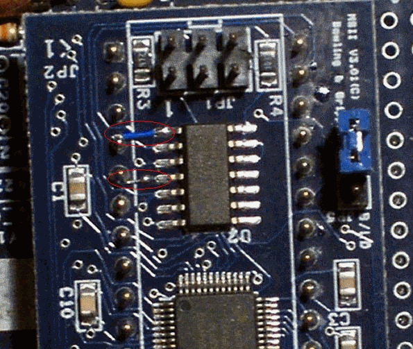
The 4-driver code is not yet ready but I thought I'd give you an idea of the modification needed on the MS2 card. The picture below shows a close-up of the MS2 card and the NAND chip on it. What I did is to solder a small jumper between pin 1 of the NAND chip and pin 4 of the card and another jumper between the via just besides pin 4 of the NAND chip (which is connected to pin 4 of the chip). The second jumper is more difficult to see because the wire is completely stripped due to how short it is. The wire is a 30-gauge wire wrap wire (single strand).
|
||||||
|
5988 Posts Member #: 2024 Formally Retired Rural Suffolk |
18th Feb, 2009 at 07:33:24am
On 17th Feb, 2009 jbelanger said:
And yes, that's the board. But it will be needed only if you have low impedance injectors. It will work with high impedance injectors but it's more expense than what's needed in that case. Jean Jean, I don't fully understand that statement. I think I understand the LM1649 chips deal with the peak/hold for low z injectors, so that is more than what's needed if I used high z injectors, but surely the board itself is still needed to give the 4 power transistors that actually drive the injectors, as the MS2 only has two ??? Rod. Schrödinger's cat - so which one am I ??? |
||||||
|
1267 Posts Member #: 831 Post Whore Montreal, Canada |
18th Feb, 2009 at 04:10:07pm
Yes you will need to add injector drivers in any case but you could just use something like 4 of these. Bolt them to the heatsink (since most of what is there would no longer be needed), add 8 resistors to the proto area and wire them in the correct way (which I'll detail later).
Edited by jbelanger on 18th Feb, 2009. |
||||||
|
5988 Posts Member #: 2024 Formally Retired Rural Suffolk |
18th Feb, 2009 at 04:28:43pm
Thanks Jean,
Schrödinger's cat - so which one am I ??? |
||||||
| Home > MS Code Discussions > Cam-aware siamese code, now with full sequential staged injection | |||||||
|
|||||||


| Page: |