
| Page: |
| Home > Technical Chat > Remote Turbo Manifold | |||||||
|
8604 Posts Member #: 573 Formerly Axel Podland |
1st May, 2009 at 11:08:01am
Dont Panic....
Saul Bellow - "A great deal of intelligence can be invested in ignorance when the need for illusion is deep."
|
||||||
 9258 Posts Member #: 123 Post Whore Betwix Harrogate and York |
1st May, 2009 at 11:20:02am
I guess needs must, but I'm not a fan of the turbo over the flywheel, not good for weight distribution, unless you have a LHD car.
Fastest 998 mini in the world? 13.05 1/4 mile 106mph
On 2nd Jan, 2013 fastcarl said:
the design shows a distinct lack of imagination, talk about starting off with a clean sheet of paper, then not bothering to fucking draw on it,lol On 20th Apr, 2012 Paul S said:
I'm mainly concerned about swirl in the runners caused by the tangential entry. |
||||||
 (2)[/url] by [url=https://www.flickr.com/photos/150672766@N03/]Rod Sugden[/url], on Fli) 5988 Posts Member #: 2024 Formally Retired Rural Suffolk |
1st May, 2009 at 11:21:47am
Re. dual widebands - my understanding is that even if you could keep the temperatures low enough, they become inaccurate under pressure which is the main reason why they can't be used before a turbo.
Schrödinger's cat - so which one am I ??? |
||||||
|
8604 Posts Member #: 573 Formerly Axel Podland |
1st May, 2009 at 11:26:59am
On 1st May, 2009 Rod S said:
Re. dual widebands - my understanding is that even if you could keep the temperatures low enough, they become inaccurate under pressure which is the main reason why they can't be used before a turbo. It would be interesting to know for sure though (fit a third one after the turbo and see if it reads the average of the two....) We discussed this a few years ago and Bat suggested that you could use a wideband upstream of the turbo if you took a small bore bleed pipe into a chamber and then fed it back downstream of the turbo. The wideband would then run at low pressure but read the upstream AFR. So I'm thinking of a couple of small compression fittings and stainless steel pipe into a 20mm bore pipe with the wideband in the end and branched into the downpipe. Saul Bellow - "A great deal of intelligence can be invested in ignorance when the need for illusion is deep."
|
||||||
|
8604 Posts Member #: 573 Formerly Axel Podland |
1st May, 2009 at 11:29:46am
On 1st May, 2009 wil_h said:
I guess needs must, but I'm not a fan of the turbo over the flywheel, not good for weight distribution, unless you have a LHD car. My thoughts were that the easiest and cheepest way to do it is use the Metro manifold and run a pipe from that. But I don't have the skills you have to build a manifold. And considering the spec of the rest of the car it probably deserves something shiney! As far as weight distribution goes, then Sturgeo can loose a few kilos. Besides I dont see many cars suffering from the weight of the driver, take The Don for example 
Agreed, the metro manifold would be cheaper, but I already have all the materials sat on the bench and would like to keep the pulses separate until the turbo flange. Saul Bellow - "A great deal of intelligence can be invested in ignorance when the need for illusion is deep."
|
||||||
|
5988 Posts Member #: 2024 Formally Retired Rural Suffolk |
1st May, 2009 at 11:41:29am
On 1st May, 2009 Paul S said:
We discussed this a few years ago and Bat suggested that you could use a wideband upstream of the turbo if you took a small bore bleed pipe into a chamber and then fed it back downstream of the turbo. The wideband would then run at low pressure but read the upstream AFR. So I'm thinking of a couple of small compression fittings and stainless steel pipe into a 20mm bore pipe with the wideband in the end and branched into the downpipe. Neat idea.... Response time might be a bit slow for closed loop control but ideal for what you want to set the siamese code up under actual boost. Got me thinking..... Schrödinger's cat - so which one am I ??? |
||||||
|
8604 Posts Member #: 573 Formerly Axel Podland |
1st May, 2009 at 12:20:09pm
Any thoughts on how to deal with the expansion?
Saul Bellow - "A great deal of intelligence can be invested in ignorance when the need for illusion is deep."
|
||||||
|
5988 Posts Member #: 2024 Formally Retired Rural Suffolk |
1st May, 2009 at 12:56:54pm
The trick with pivoted link arm(s) is to get the pivot angle (in two planes) correct and then the length and starting angle in the third plane exactly right to match movement in three planes.
Schrödinger's cat - so which one am I ??? |
||||||
 1346 Posts Member #: 2340 Post Whore Dublin Ireland |
1st May, 2009 at 01:00:00pm
I am building the same Idea for a GT2056 Paul for this years race,
On 17th Feb, 2009 Rob H said:
I find the easiest way is to super glue the bolt to the end of one of my fingers. ______________________________________________________ |
||||||
|
8604 Posts Member #: 573 Formerly Axel Podland |
1st May, 2009 at 01:14:58pm
Paul H, interesting, but I'm not sure that I understand or agree with your thinking.
Saul Bellow - "A great deal of intelligence can be invested in ignorance when the need for illusion is deep."
|
||||||
|
5988 Posts Member #: 2024 Formally Retired Rural Suffolk |
1st May, 2009 at 01:47:19pm
The other thing to bear in mind with the "flexis" is that they are designed for flexing only, not changes in length.
Schrödinger's cat - so which one am I ??? |
||||||
|
1346 Posts Member #: 2340 Post Whore Dublin Ireland |
1st May, 2009 at 01:54:22pm
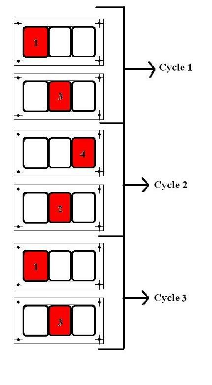
Ok the way I look at your idea Paul is that it creates a Square wave type pattern across the Turbo inlet flange where as the old metro Turbo type idea as in the attached pic gives a much smother snake like pulse pattern, more a kin to the sine wave which is harmonic which should give smooth laminar flow allowing the turbine to spool smoothly.
Edited by PaulH on 1st May, 2009. On 17th Feb, 2009 Rob H said:
I find the easiest way is to super glue the bolt to the end of one of my fingers. ______________________________________________________ |
||||||
|
8604 Posts Member #: 573 Formerly Axel Podland |
1st May, 2009 at 04:01:52pm
Not sure about that.
Saul Bellow - "A great deal of intelligence can be invested in ignorance when the need for illusion is deep."
|
||||||
|
1346 Posts Member #: 2340 Post Whore Dublin Ireland |
1st May, 2009 at 05:08:03pm
Look forward to see how it works for you Paul I'm not after out and out power on this one, more a smoth torque and high cornering speeds. On 17th Feb, 2009 Rob H said:
I find the easiest way is to super glue the bolt to the end of one of my fingers. ______________________________________________________ |
||||||
 9502 Posts Member #: 1023 Post Whore Doncaster, South Yorkshire |
1st May, 2009 at 05:41:36pm
im keeping my eye on this thread... where's the pop corn simile Yes i moved to the darkside |
||||||
|
Forum Mod 10979 Posts Member #: 17 ***16*** SouthPark, Colorado |
1st May, 2009 at 06:10:12pm
I have not much to add i'm afraid - but that Peter1071s wrote quite a lot about this kind of stuff I recall. For all the bad things we can say - he did (does?) appear to know a fair bit so if he hasn't deleted the posts, then you might find some useful info? On 17th Nov, 2014 Tom Fenton said:
Sorry to say My Herpes are no better Ready to feel Ancient ??? This is 26 years old as of 2022 https://youtu.be/YQQokcoOzeY |
||||||
|
8604 Posts Member #: 573 Formerly Axel Podland |
2nd May, 2009 at 05:22:51pm
Good progress so far....
Saul Bellow - "A great deal of intelligence can be invested in ignorance when the need for illusion is deep."
|
||||||
|
1346 Posts Member #: 2340 Post Whore Dublin Ireland |
2nd May, 2009 at 07:09:53pm
Whats to OD and ID of that tube Paul. On 17th Feb, 2009 Rob H said:
I find the easiest way is to super glue the bolt to the end of one of my fingers. ______________________________________________________ |
||||||
|
1346 Posts Member #: 2340 Post Whore Dublin Ireland |
2nd May, 2009 at 07:09:58pm
Whats to OD and ID of that tube Paul. On 17th Feb, 2009 Rob H said:
I find the easiest way is to super glue the bolt to the end of one of my fingers. ______________________________________________________ |
||||||
|
4314 Posts Member #: 700 Formerly British Open Classic The West Country |
2nd May, 2009 at 07:18:42pm
Look good,
Isambard Kingdom Brunel said:
Nothing is impossible if you are an Engineer |
||||||
 12307 Posts Member #: 565 Carlos Fandango Burnham-on-Crouch, Essex |
2nd May, 2009 at 07:59:51pm
Looks good Paul,
On 28th Aug, 2011 Kean said:
At the risk of being sigged... Joe, do you have a photo of your tool? http://www.turbominis.co.uk/forums/index.p...9064&lastpost=1 https://joe1977.imgbb.com/ |
||||||
|
8604 Posts Member #: 573 Formerly Axel Podland |
2nd May, 2009 at 08:27:28pm
Paul, the pipe is 28/33mm ish.
Saul Bellow - "A great deal of intelligence can be invested in ignorance when the need for illusion is deep."
|
||||||
 22 Posts Member #: 710 Member Amsterdam, The Netherlands |
3rd May, 2009 at 09:58:11am
Hi Paul,
|
||||||
|
22 Posts Member #: 710 Member Amsterdam, The Netherlands |
3rd May, 2009 at 10:05:28am
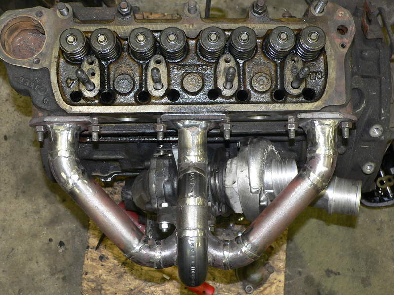
This is a photo from my manifold. The flow in the center pipe will be okay, but the outside ones will lose pulse/momentum.
Edited by thimo on 3rd May, 2009. |
||||||
|
8604 Posts Member #: 573 Formerly Axel Podland |
3rd May, 2009 at 10:39:54am
Thimo, you may well have a very valid point and a collector style joint would be better.
Saul Bellow - "A great deal of intelligence can be invested in ignorance when the need for illusion is deep."
|
||||||
| Home > Technical Chat > Remote Turbo Manifold | |||||||
|
|||||||


| Page: |