| Page: |
| Home > Paul S trials and testing > AFR Sample Chambers | |||||||
|
8604 Posts Member #: 573 Formerly Axel Podland |
19th Jun, 2009 at 02:56:31pm
Knocked this out as a first attempt.
Saul Bellow - "A great deal of intelligence can be invested in ignorance when the need for illusion is deep."
|
||||||
 2406 Posts Member #: 341 aka T2clubby South Staffs |
19th Jun, 2009 at 03:11:42pm
Is the stainless take off for EGT?
|
||||||
|
8604 Posts Member #: 573 Formerly Axel Podland |
19th Jun, 2009 at 03:46:02pm
No, stainless take-off for wideband sensor pre-turbo, so that you don't pressurise the sensor and damage it. Saul Bellow - "A great deal of intelligence can be invested in ignorance when the need for illusion is deep."
|
||||||
 (2)[/url] by [url=https://www.flickr.com/photos/150672766@N03/]Rod Sugden[/url], on Fli) 5988 Posts Member #: 2024 Formally Retired Rural Suffolk |
19th Jun, 2009 at 03:48:44pm
My only thought would be make the "chamber" a little bit bigger relative to the downstream pipe. It just "looks" as if downsteam flow conditions may distort the flow from the small stainless pipe.
Edited by Rod S on 19th Jun, 2009. Schrödinger's cat - so which one am I ??? |
||||||
|
8604 Posts Member #: 573 Formerly Axel Podland |
19th Jun, 2009 at 04:09:47pm
The actual sensor ports are in line with the incoming pipe that is 4mm bore.
Saul Bellow - "A great deal of intelligence can be invested in ignorance when the need for illusion is deep."
|
||||||
 2406 Posts Member #: 341 aka T2clubby South Staffs |
19th Jun, 2009 at 04:46:51pm
Ah I understand now, nice work.
|
||||||
|
1267 Posts Member #: 831 Post Whore Montreal, Canada |
19th Jun, 2009 at 05:11:02pm
I don't know if you intend to put it on the same exhaust as the one you were using before but if it's the case and you still have the sensor bungs on it, you could put one sensor in the original bung and one on this new chamber and compare readings.
|
||||||
|
8604 Posts Member #: 573 Formerly Axel Podland |
19th Jun, 2009 at 05:13:51pm
No, its for the turbo manifold, so all new.
Saul Bellow - "A great deal of intelligence can be invested in ignorance when the need for illusion is deep."
|
||||||
|
8604 Posts Member #: 573 Formerly Axel Podland |
20th Jun, 2009 at 11:43:02am
Now tacked on the downpipe:
Saul Bellow - "A great deal of intelligence can be invested in ignorance when the need for illusion is deep."
|
||||||
 1849 Posts Member #: 672 The oversills police Oslo, Norway |
20th Jun, 2009 at 12:18:46pm
I thought this was for the sidemount turbo engine? |
||||||
|
8604 Posts Member #: 573 Formerly Axel Podland |
20th Jun, 2009 at 12:30:09pm
On 20th Jun, 2009 miniminor63 said:
I thought this was for the sidemount turbo engine? This one is for the 998 Turbo. I'll be doing something similar for the side mount turbo in the Miglia if this works OK. Saul Bellow - "A great deal of intelligence can be invested in ignorance when the need for illusion is deep."
|
||||||
|
8604 Posts Member #: 573 Formerly Axel Podland |
21st Jun, 2009 at 12:11:25pm
Nearly finished, just didn't buy enough of the 6mm tube.
Saul Bellow - "A great deal of intelligence can be invested in ignorance when the need for illusion is deep."
|
||||||
 12307 Posts Member #: 565 Carlos Fandango Burnham-on-Crouch, Essex |
21st Jun, 2009 at 12:22:49pm
very nice Paul :)
On 28th Aug, 2011 Kean said:
At the risk of being sigged... Joe, do you have a photo of your tool? http://www.turbominis.co.uk/forums/index.p...9064&lastpost=1 https://joe1977.imgbb.com/ |
||||||
 (2)[/url] by [url=https://www.flickr.com/photos/150672766@N03/]Rod Sugden[/url], on Fli) 5988 Posts Member #: 2024 Formally Retired Rural Suffolk |
21st Jun, 2009 at 12:51:53pm
The only potential issue I see is length of the small bore tubes, or are you going to run the second one in such a way it is the same length as the first ??? Schrödinger's cat - so which one am I ??? |
||||||
|
8604 Posts Member #: 573 Formerly Axel Podland |
21st Jun, 2009 at 01:25:18pm
No, I plan on taking the shortest route.
Saul Bellow - "A great deal of intelligence can be invested in ignorance when the need for illusion is deep."
|
||||||
|
3569 Posts Member #: 655 Post Whore Northern Ireland |
21st Jun, 2009 at 02:10:09pm
Might have been better dumping them further down the exhaust, so there is less chance of the ex-tubine gasses shooting up the tube, contaminating your sample.
9.85 @ 145mph
|
||||||
|
8604 Posts Member #: 573 Formerly Axel Podland |
21st Jun, 2009 at 02:13:37pm
On 21st Jun, 2009 stevieturbo said:
Might have been better dumping them further down the exhaust, so there is less chance of the ex-tubine gasses shooting up the tube, contaminating your sample. Or better still, vent the post sensor to atmos Good point. That may well happen at low load. I'm hoping that under boost there will be enough pressure to keep things moving in the right direction. I'm planning on having a proven setup in NA mode, so that I'll only need to be concerned with AFRs under boost. Can always modify it later. Saul Bellow - "A great deal of intelligence can be invested in ignorance when the need for illusion is deep."
|
||||||
|
3004 Posts Member #: 2500 Post Whore Buckinghamshire |
21st Jun, 2009 at 04:12:37pm
You guys are so far ahead of me I dont really follow these threads, but can you tell me why you want to move the oxygen sensor away from the manifold instead of just putting it in a boss close to the turbo outlet ?.Is it because you want to sample for each exhaust port ?. |
||||||
|
8604 Posts Member #: 573 Formerly Axel Podland |
21st Jun, 2009 at 04:21:07pm
Yes, with port injection, the inner and outer cylinders run at different AFRs unless the timing of the injection is precise, so we need to measure inner and outer AFRs separately. Saul Bellow - "A great deal of intelligence can be invested in ignorance when the need for illusion is deep."
|
||||||
|
3569 Posts Member #: 655 Post Whore Northern Ireland |
21st Jun, 2009 at 06:02:44pm
On 21st Jun, 2009 Paul S said:
On 21st Jun, 2009 stevieturbo said:
Might have been better dumping them further down the exhaust, so there is less chance of the ex-tubine gasses shooting up the tube, contaminating your sample. Or better still, vent the post sensor to atmos Good point. That may well happen at low load. I'm hoping that under boost there will be enough pressure to keep things moving in the right direction. I'm planning on having a proven setup in NA mode, so that I'll only need to be concerned with AFRs under boost. Can always modify it later. Given the small diameter of the feed tubes ( for obvious reasons ), I think the exhaust gases exiting the turbo, could shoot straight up the tube. More so as the tubes are almost pointing at the turbine exit. There simply wouldnt be enough volumne of gas at the higher pressure to resist it. Even if the tubes were cut/welded in at an extreme angle.... In fact at an angle like some of the crankcase evac systems use, so that it actually tends to draw any gases into the exhaust stream. 9.85 @ 145mph
|
||||||
|
3569 Posts Member #: 655 Post Whore Northern Ireland |
21st Jun, 2009 at 06:06:23pm
http://www.summitracing.com/parts/DTC-85-100950/?image=large
9.85 @ 145mph
|
||||||
|
8604 Posts Member #: 573 Formerly Axel Podland |
21st Jun, 2009 at 06:13:15pm
Ideally the two pipes would join the downpipe after the join but that would be a fabrication and installation nightmare.
Saul Bellow - "A great deal of intelligence can be invested in ignorance when the need for illusion is deep."
|
||||||
 6743 Posts Member #: 828 Post Whore uranus |
21st Jun, 2009 at 07:14:56pm
i think both paul and steve are right ,at low rpm i can see steves scenario playing out ,particularly between pulses ,and once the turbo creats some back pressure then it changes around to reading as it should..
Medusa + injection = too much torque for the dyno ..https://youtu.be/qg5o0_tJxYM |
||||||
|
1267 Posts Member #: 831 Post Whore Montreal, Canada |
21st Jun, 2009 at 09:33:56pm
At low RPM. it will also depend on where the exhaust gas speed is higher. Due to venturi effect it will have a tendency to go where the speed is higher.
|
||||||
 6274 Posts Member #: 509 Post Whore Isle of Man |
21st Jun, 2009 at 11:16:58pm
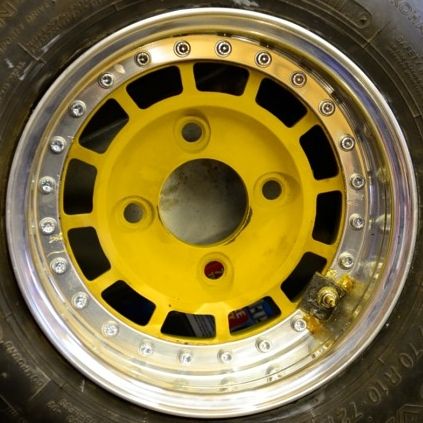
i just looked at the first pic, and thought you had welded your wb sensor to its boss
"Turbo's make torque, and torque makes fun"
|
||||||
| Home > Paul S trials and testing > AFR Sample Chambers | |||||||
|
|||||||
| Page: |


