
| Page: |
| Home > A-Series EFI / Injection > AFR Sample Chambers - Take 3 - R | |||||||
|
1303 Posts Member #: 30 Post Whore Epsom, Surrey |
17th Jul, 2009 at 02:29:30pm
this is all very interesting stuff and good to see some progresion.
|
||||||
 (2)[/url] by [url=https://www.flickr.com/photos/150672766@N03/]Rod Sugden[/url], on Fli) 5988 Posts Member #: 2024 Formally Retired Rural Suffolk |
19th Jul, 2009 at 05:42:22pm
I do actually have a third one available which I will (eventually) fit in the bottom of the downpipe. Unfortunately it is a different make (Innovate) which means I may not be able to get identical calibrations as you can only calibrate (easily) at one end of the range, ie free air.
Schrödinger's cat - so which one am I ??? |
||||||
 6744 Posts Member #: 828 Post Whore uranus |
19th Jul, 2009 at 09:38:01pm
thats intersting rod , the air fuel imbalance flips at a higher rpm ,and the outers get rich .it would be very intersting to see and drive log of that setup ,with a single sensor in the down pipe as well ,but i guess your motivated to get boosty wiv it ? Medusa + injection = too much torque for the dyno ..https://youtu.be/qg5o0_tJxYM |
||||||
|
5988 Posts Member #: 2024 Formally Retired Rural Suffolk |
19th Jul, 2009 at 10:29:47pm
Robert, I've seen the AFRs flip even at low RPM, just using a standard carb and twin widebands on the N/A MG twin downpipe manifold, just from going from on choke to off choke.
Schrödinger's cat - so which one am I ??? |
||||||
 1767 Posts Member #: 9165 Previously josh4444 Australia, brisbane |
28th Nov, 2013 at 11:07:46am
an old thread i know..
|
||||||
|
8604 Posts Member #: 573 Formerly Axel Podland |
28th Nov, 2013 at 11:25:56am
Not enough users/data to identify the "sweet spot".
Saul Bellow - "A great deal of intelligence can be invested in ignorance when the need for illusion is deep."
|
||||||
 10020 Posts Member #: 1456 Mongo Barnsley, South Flatcapshire |
28th Nov, 2013 at 11:35:36am
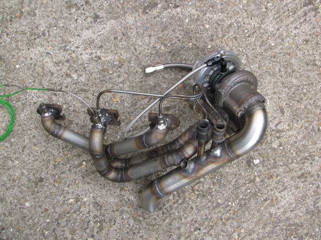
I do like that manifold setup If something is worth doing, it's worth doing half of. |
||||||
|
8604 Posts Member #: 573 Formerly Axel Podland |
28th Nov, 2013 at 11:38:50am
On 28th Nov, 2013 John said:
I do like that manifold setup  It's very good................... at propping the garage door open. Saul Bellow - "A great deal of intelligence can be invested in ignorance when the need for illusion is deep."
|
||||||
|
10020 Posts Member #: 1456 Mongo Barnsley, South Flatcapshire |
28th Nov, 2013 at 11:43:46am
I'll take it off your hands and replace it with a nice wedge of wood in that case If something is worth doing, it's worth doing half of. |
||||||
|
5988 Posts Member #: 2024 Formally Retired Rural Suffolk |
28th Nov, 2013 at 12:16:06pm
As Paul says, "Not enough users/data to identify the "sweet spot"" yet.
Schrödinger's cat - so which one am I ??? |
||||||
|
8604 Posts Member #: 573 Formerly Axel Podland |
28th Nov, 2013 at 01:18:06pm
Of course, the problem is that the exhaust gas going to the sample chambers is bypassing the turbo. This could slightly raise the rpm at which the turbo starts producing boost. It's not really an issue once on boost as the wastegate is open anyway.
Saul Bellow - "A great deal of intelligence can be invested in ignorance when the need for illusion is deep."
|
||||||
|
1767 Posts Member #: 9165 Previously josh4444 Australia, brisbane |
29th Nov, 2013 at 09:02:14am
ok first of thanks guys for helping share your work and outcomes this is why the forum is so good!
|
||||||
|
8604 Posts Member #: 573 Formerly Axel Podland |
29th Nov, 2013 at 10:26:13am
I did receive some negative comment for this:
Saul Bellow - "A great deal of intelligence can be invested in ignorance when the need for illusion is deep."
|
||||||
|
1767 Posts Member #: 9165 Previously josh4444 Australia, brisbane |
30th Nov, 2013 at 12:26:44am
ok so ive gotten my materials
|
||||||
|
1767 Posts Member #: 9165 Previously josh4444 Australia, brisbane |
30th Nov, 2013 at 10:23:25am
well ive made the chambers yet to put the feed fitting in and attach them to the mani tho
|
||||||
|
8604 Posts Member #: 573 Formerly Axel Podland |
30th Nov, 2013 at 11:59:26am
I would do it as the last photo.
Saul Bellow - "A great deal of intelligence can be invested in ignorance when the need for illusion is deep."
|
||||||
|
5988 Posts Member #: 2024 Formally Retired Rural Suffolk |
30th Nov, 2013 at 01:18:15pm
^^^ as above.
Edited by Rod S on 30th Nov, 2013. Schrödinger's cat - so which one am I ??? |
||||||
|
1767 Posts Member #: 9165 Previously josh4444 Australia, brisbane |
30th Nov, 2013 at 09:25:40pm
will do im off to finish them |
||||||
|
1767 Posts Member #: 9165 Previously josh4444 Australia, brisbane |
1st Dec, 2013 at 12:52:22am
right this is what ive got so far
Edited by Turbo This.. on 1st Dec, 2013. |
||||||
|
5988 Posts Member #: 2024 Formally Retired Rural Suffolk |
1st Dec, 2013 at 08:46:00am
Looking good....
Schrödinger's cat - so which one am I ??? |
||||||
|
1767 Posts Member #: 9165 Previously josh4444 Australia, brisbane |
1st Dec, 2013 at 12:58:24pm
cheers rod ill have a good look tomorrow
|
||||||
|
1767 Posts Member #: 9165 Previously josh4444 Australia, brisbane |
3rd Dec, 2013 at 10:36:44am
i when into my hydraulics shop and tried to exchange the brass fittings i found out that the ss ones are like 25 bucks each (need 4 plus a plug) they also said that the fittings will be good up to 1600 F? i then asked about the fittings holding onto the pipes they said bring them in if they do we will swap them for free on the spot
|
||||||
|
5988 Posts Member #: 2024 Formally Retired Rural Suffolk |
3rd Dec, 2013 at 11:48:51am
The melting point of brass is about 900C so the ones in your manifold will get pretty close to that, maybe exceed it (esp. if you are wrapping it to keep the heat in).
Edited by Rod S on 3rd Dec, 2013. Schrödinger's cat - so which one am I ??? |
||||||
|
1767 Posts Member #: 9165 Previously josh4444 Australia, brisbane |
4th Dec, 2013 at 09:00:56am
will 6mm OD fitting be ok on the ss 1/4" (6.35mm OD) tubing i already have?
|
||||||
|
5988 Posts Member #: 2024 Formally Retired Rural Suffolk |
4th Dec, 2013 at 09:32:09am
On 4th Dec, 2013 Turbo This.. said:
will 6mm OD fitting be ok on the ss 1/4" (6.35mm OD) tubing i already have? will that 0.35mm make it not seal or grip the tube? im going to use 90 degree ones for space reasons mainly also less tube due to the more straight line approach un less they need to be equal length? I didn't realise your tube was imperial. I doubt you would get 1/4" tube to go into the metric fittings - because stainless is harder than brass/copper (so harder to squash down onto the tube), the ID of the ferrules will be very close to 6mm, probably not as large as 6.35 The obvious question would be why don't you use 6mm tubing but a quick search on eBay AUS doesn't show any (apart from importing from the UK !!!). Very strange, but I'm sure you can source it somewhere in Aus. Otherwise just try it - it may actually be 6mm, just sold as 1/4" (have you actually measured it ?), or the ferrules my just be large enough, or you could take a very light skim off the tube just at the ends, before bending it. 90 degree fittings are a good idea if space dictates it but you may have to play with tapping the holes (assuming you use the correct taper tap) to make sure they lock up on their threads pointing the way you want them to. My sample tubes are different lengths and, within the data logging speed, I see no difference in response times. Schrödinger's cat - so which one am I ??? |
||||||
| Home > A-Series EFI / Injection > AFR Sample Chambers - Take 3 - R | |||||||
|
|||||||


| Page: |