
| Page: |
| Home > Show Us Yours! > Thought it time I finished a design I started 4 years ago....... | |||||||
|
1425 Posts Member #: 690 Post Whore Norfolk |
1st Nov, 2009 at 04:13:37pm
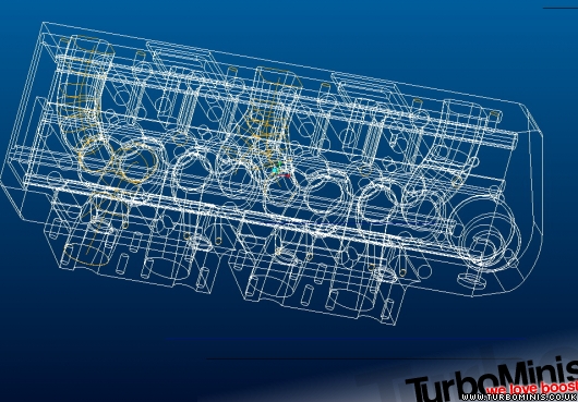
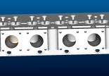
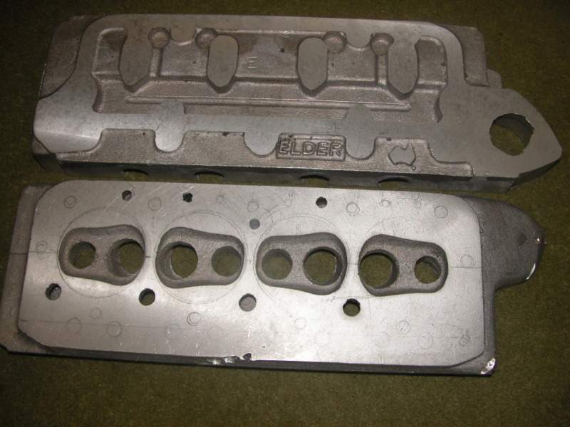
Almost to the month back in 2005 I started this - then stopped in Jan 2006 when I got into the K conversion - so I've pressed on in the past few weeks to get it together.
If Carling made Mini engines
|
||||||
 12307 Posts Member #: 565 Carlos Fandango Burnham-on-Crouch, Essex |
1st Nov, 2009 at 04:19:12pm
wheres the heater take off? On 28th Aug, 2011 Kean said:
At the risk of being sigged... Joe, do you have a photo of your tool? http://www.turbominis.co.uk/forums/index.p...9064&lastpost=1 https://joe1977.imgbb.com/ |
||||||
|
1425 Posts Member #: 690 Post Whore Norfolk |
1st Nov, 2009 at 04:21:22pm
there is an additional piece which bolts to that side of the head to complete the water circuit - you can see some recessed machining at that end in the pic ready to accept it.
If Carling made Mini engines
|
||||||
|
Forum Mod  5933 Posts Member #: 784 9 times Avon Park Class C winner Milton Keynes |
1st Nov, 2009 at 04:23:55pm
Whats the stud pattern on the inlets?
I seriously doubt it! |
||||||
|
1425 Posts Member #: 690 Post Whore Norfolk |
1st Nov, 2009 at 04:38:10pm
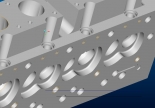
Paul, what I wanted to do with my design was to keep the inlet tracts as straight as possible, this isn't as easy as it sounds when you start looking at packing throttle bodies into the spacing that two inlets close together require. The stud pattern is to suit "single" throttle bodies which I can make fit this spacing, the other option I'll probably take into account look is bolt on stubs for M/C carbs. You can't see in that shot but the inlets are down draught to a good degree to increase the length of the short turn radius.
If Carling made Mini engines
|
||||||
|
12307 Posts Member #: 565 Carlos Fandango Burnham-on-Crouch, Essex |
1st Nov, 2009 at 05:18:41pm
I presume this'll be ally John?
On 28th Aug, 2011 Kean said:
At the risk of being sigged... Joe, do you have a photo of your tool? http://www.turbominis.co.uk/forums/index.p...9064&lastpost=1 https://joe1977.imgbb.com/ |
||||||
|
1425 Posts Member #: 690 Post Whore Norfolk |
1st Nov, 2009 at 05:22:28pm
Hi Joe - yes ally - billet as usual from me.lol!
If Carling made Mini engines
|
||||||
|
12307 Posts Member #: 565 Carlos Fandango Burnham-on-Crouch, Essex |
1st Nov, 2009 at 05:29:49pm
LOL,
On 28th Aug, 2011 Kean said:
At the risk of being sigged... Joe, do you have a photo of your tool? http://www.turbominis.co.uk/forums/index.p...9064&lastpost=1 https://joe1977.imgbb.com/ |
||||||
|
1425 Posts Member #: 690 Post Whore Norfolk |
1st Nov, 2009 at 05:42:22pm
Joe - port spacing is 66mm for the end pairings!
If Carling made Mini engines
|
||||||
|
12307 Posts Member #: 565 Carlos Fandango Burnham-on-Crouch, Essex |
1st Nov, 2009 at 06:03:32pm
thats significantly better, i guess probably about 85mm between the middle two, thats getting on for a third less than mine for the total length,
On 28th Aug, 2011 Kean said:
At the risk of being sigged... Joe, do you have a photo of your tool? http://www.turbominis.co.uk/forums/index.p...9064&lastpost=1 https://joe1977.imgbb.com/ |
||||||
|
12307 Posts Member #: 565 Carlos Fandango Burnham-on-Crouch, Essex |
1st Nov, 2009 at 06:15:10pm
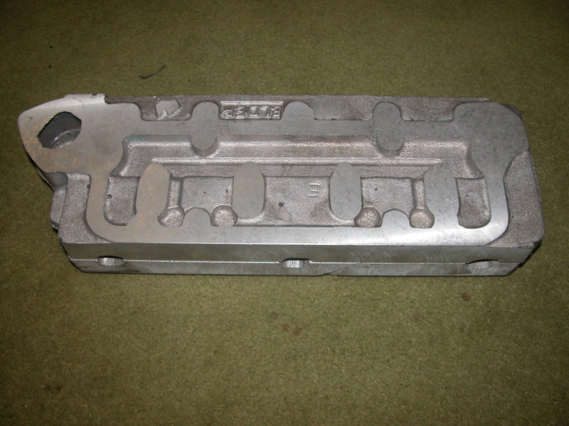
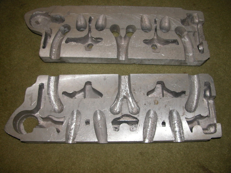
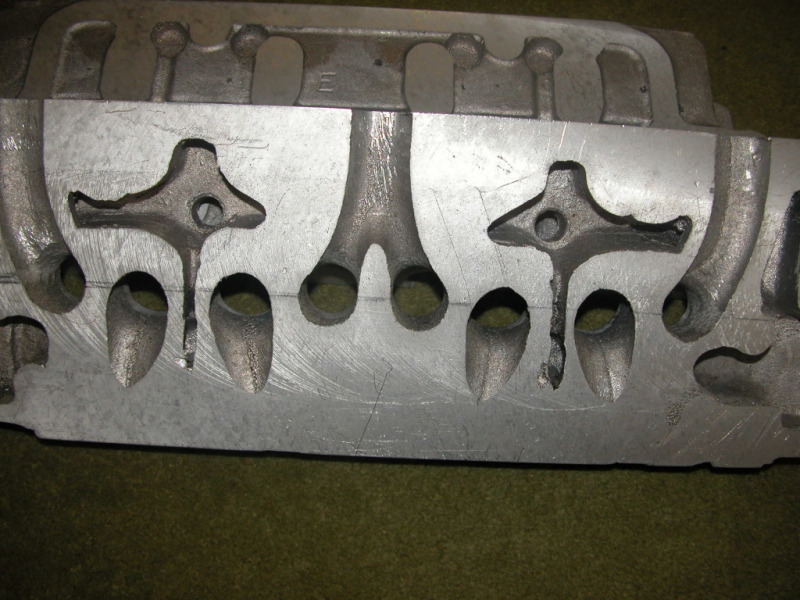
also have you seen the pics of cut up elder 7&8 port heads? On 28th Aug, 2011 Kean said:
At the risk of being sigged... Joe, do you have a photo of your tool? http://www.turbominis.co.uk/forums/index.p...9064&lastpost=1 https://joe1977.imgbb.com/ |
||||||
|
1425 Posts Member #: 690 Post Whore Norfolk |
1st Nov, 2009 at 06:20:59pm
yip those are injector holes facing the back of the inlet valves
If Carling made Mini engines
|
||||||
|
1425 Posts Member #: 690 Post Whore Norfolk |
1st Nov, 2009 at 06:54:04pm
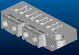
A couple of pics with less lines.
If Carling made Mini engines
|
||||||
|
12307 Posts Member #: 565 Carlos Fandango Burnham-on-Crouch, Essex |
1st Nov, 2009 at 06:54:37pm
the rest of the thread is worth a read too,
On 28th Aug, 2011 Kean said:
At the risk of being sigged... Joe, do you have a photo of your tool? http://www.turbominis.co.uk/forums/index.p...9064&lastpost=1 https://joe1977.imgbb.com/ |
||||||
 9502 Posts Member #: 1023 Post Whore Doncaster, South Yorkshire |
1st Nov, 2009 at 09:06:09pm
im interested, for the future, looks good i have some pics on file some where dont know what head there from im off for a dig Edited by Brett on 1st Nov, 2009. Yes i moved to the darkside |
||||||
| Home > Show Us Yours! > Thought it time I finished a design I started 4 years ago....... | |||||||
|
|||||||


| Page: |