
| Page: |
| Home > Technical Chat > Plenums and ram pipes | |||||||
|
8215 Posts Member #: 90 Post Whore Somewhere around Swindon |
23rd May, 2010 at 06:15:31pm
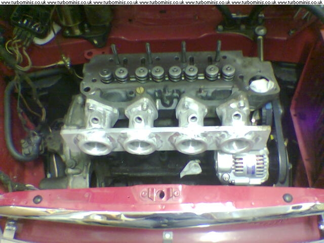
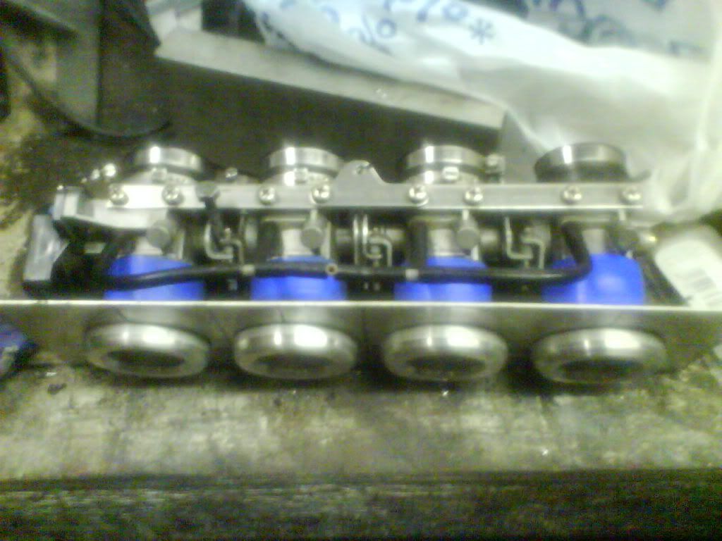
After reading though a few threads ie Joes 7 port and Rods 5 port i noticed that the ram pipes protrude into the plenum significently
Crystal Sound Audio said:
Why wolfie...you should have your name as Fuckfaceshithead ! "A common mistake that people make when trying to design something completely foolproof is to underestimate the ingenuity of complete fools."-Douglas Adams |
||||||
 12307 Posts Member #: 565 Carlos Fandango Burnham-on-Crouch, Essex |
23rd May, 2010 at 06:58:20pm
mine are like that as it was easier to do it that way,
On 28th Aug, 2011 Kean said:
At the risk of being sigged... Joe, do you have a photo of your tool? http://www.turbominis.co.uk/forums/index.p...9064&lastpost=1 https://joe1977.imgbb.com/ |
||||||
 3329 Posts Member #: 184 Senior Member Melton Mowbray, Pie Country |
23rd May, 2010 at 07:42:12pm
Putting a proper stub stack type inlet has the same benefits in a plenum as it does in an air filer. Although having squared off edges like the two shown will not be as good as a stub stack or ram pipe design. http://www.twin-turbo.co.uk
|
||||||
|
8604 Posts Member #: 573 Formerly Axel Podland |
23rd May, 2010 at 08:10:05pm
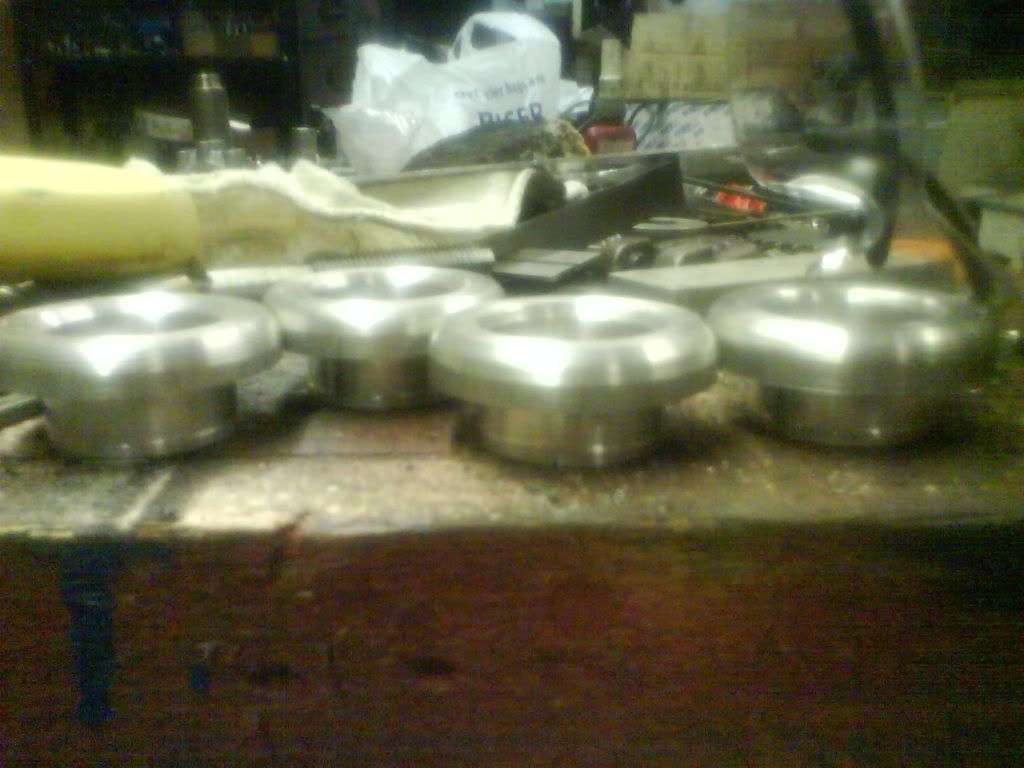
I use these bellmouths, basically because the yelow bible suggests that it is one of the best shapes.
Saul Bellow - "A great deal of intelligence can be invested in ignorance when the need for illusion is deep."
|
||||||
|
8215 Posts Member #: 90 Post Whore Somewhere around Swindon |
23rd May, 2010 at 08:10:54pm
where are they from Paul?
Crystal Sound Audio said:
Why wolfie...you should have your name as Fuckfaceshithead ! "A common mistake that people make when trying to design something completely foolproof is to underestimate the ingenuity of complete fools."-Douglas Adams |
||||||
|
8604 Posts Member #: 573 Formerly Axel Podland |
23rd May, 2010 at 08:14:42pm
I machined them up from solid.
Saul Bellow - "A great deal of intelligence can be invested in ignorance when the need for illusion is deep."
|
||||||
|
8215 Posts Member #: 90 Post Whore Somewhere around Swindon |
23rd May, 2010 at 08:24:55pm
Missed alot of your thread Paul bloody clever stuff! Crystal Sound Audio said:
Why wolfie...you should have your name as Fuckfaceshithead ! "A common mistake that people make when trying to design something completely foolproof is to underestimate the ingenuity of complete fools."-Douglas Adams |
||||||
|
8604 Posts Member #: 573 Formerly Axel Podland |
23rd May, 2010 at 08:40:13pm
Thanks.
Saul Bellow - "A great deal of intelligence can be invested in ignorance when the need for illusion is deep."
|
||||||
 8297 Posts Member #: 408 Turbo Love Palace Fool Aylesbury |
23rd May, 2010 at 10:23:49pm
I used them on mine as I read that the bell mouth design helps to keep air speed up as it changes direction. Sharp edges cause masive losses in air velocity.
https://www.facebook.com/pages/Fusion-Fabri..._homepage_panel
|
||||||
 11046 Posts Member #: 965 Post Whore Preston On The Brook |
24th May, 2010 at 12:10:36am
My machinist made an error interpreting my drawings, so I ended up with a comprimise to recover from said mistake, but, there is a 6mm radius leading to a bell mouth almost the full length, so it at least has to be better than just a straight 38mm opening :)
Edited by Sprocket on 24th May, 2010. On 26th Oct, 2004 TurboDave16v said:
Is it A-Series only? I think it should be... So when some joey comes on here about how his 16v turbo vauxhall is great compared to ours, he can be given the 'bird'... On 26th Oct, 2004 Tom Fenton said:
Yep I agree with TD........ |
||||||
 263 Posts Member #: 115 Senior Member Austria, near Vienna |
28th May, 2010 at 07:33:55pm
http://www.minifreunde.at/harry/links/inletsystem.htm
Bimmer Twinky headed and turboed A-Series:
|
||||||
 (2)[/url] by [url=https://www.flickr.com/photos/150672766@N03/]Rod Sugden[/url], on Fli) 5988 Posts Member #: 2024 Formally Retired Rural Suffolk |
28th May, 2010 at 09:41:25pm
I didn't spot this when it was first posted....
Schrödinger's cat - so which one am I ??? |
||||||
|
1267 Posts Member #: 831 Post Whore Montreal, Canada |
28th May, 2010 at 10:25:14pm
On 28th May, 2010 Rod S said:
I personally tend to think that once the plenum is under pressure (ie, boost) the exact shape becomes less relevant. I would think that fluid dynamics would still apply no matter what the pressure is. Of course, the optimum shape and size might be affected but the principle should still be valid. And even under boost, optimizing flow will be beneficial since you will achieve the same air mass flow with less boost. Jean |
||||||
|
5988 Posts Member #: 2024 Formally Retired Rural Suffolk |
29th May, 2010 at 08:13:51am
Yes, the rules still apply - my simplistic point is that on a normally aspirated engine the pressure difference (which drives the air mass flow) would be very low at that position and can't be increased, so optimizing the flow regime is very important.
Schrödinger's cat - so which one am I ??? |
||||||
 6753 Posts Member #: 828 Post Whore uranus |
29th May, 2010 at 09:14:16am
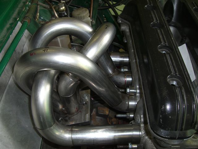
Medusa + injection = too much torque for the dyno ..https://youtu.be/qg5o0_tJxYM |
||||||
|
5988 Posts Member #: 2024 Formally Retired Rural Suffolk |
29th May, 2010 at 10:59:06am
Interesting Robert,
Schrödinger's cat - so which one am I ??? |
||||||
|
8604 Posts Member #: 573 Formerly Axel Podland |
29th May, 2010 at 01:16:55pm
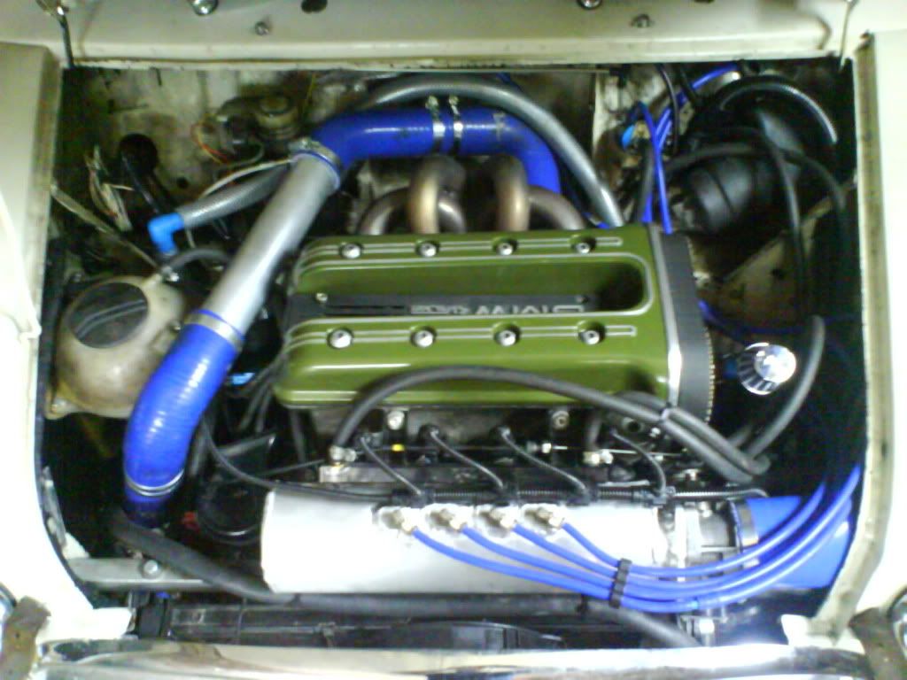
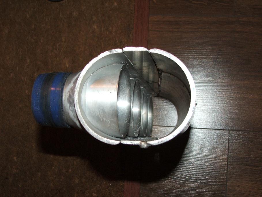
Well, this is the current state of the Miglia Turbo inlet:
Saul Bellow - "A great deal of intelligence can be invested in ignorance when the need for illusion is deep."
|
||||||
|
5988 Posts Member #: 2024 Formally Retired Rural Suffolk |
29th May, 2010 at 01:31:19pm
What volume are you using inside there Paul ???
Schrödinger's cat - so which one am I ??? |
||||||
|
6753 Posts Member #: 828 Post Whore uranus |
29th May, 2010 at 01:49:04pm
On 29th May, 2010 Rod S said:
Interesting Robert, Do you know if that is measured or computer modelled ??? And under steady state (flow bench) or real individual pulses ??? At least the ram pipes / stubs, whatever you want to call them, protrude a fair way into the plenum.... no , im sorry rod , no more info on that ,, i found it interesting that the pressure gets gradually less in the inlets as you go from small end to large . Medusa + injection = too much torque for the dyno ..https://youtu.be/qg5o0_tJxYM |
||||||
|
8604 Posts Member #: 573 Formerly Axel Podland |
29th May, 2010 at 02:09:20pm
On 29th May, 2010 Rod S said:
What volume are you using inside there Paul ??? I've worked on 1.3 - 1.6 times the engine capacity which I've read on here and other sites is the optimum for forced induction but it is giving me lots of problems fitting it all physically in. Yours looks smaller overall (although obviously a photo can be very deceptive). It's around 1850cc for the cylinder (10cm dia by 23.5cm long), so it should be around the correct volume. By the time I add the taper it will be near the 1.6 times engine capacity. The 998T is running something similar, but a bit shorter, so it is also running at around the 1.6. Although that has much longer runners, overall it gives a very torquey feel and revs well. Saul Bellow - "A great deal of intelligence can be invested in ignorance when the need for illusion is deep."
|
||||||
|
5988 Posts Member #: 2024 Formally Retired Rural Suffolk |
29th May, 2010 at 02:14:09pm
On 29th May, 2010 robert said:
.... i found it interesting that the pressure gets gradually less in the inlets as you go from small end to large . Me too, as if the taper was too great and putting excess pressure in the small end. Also noteable, the first two (from inlet end) get the lowest pressure at their first edge, almost as if the shape of the trumpet at 90degree to the mass flow is acting classic Bernouili (ie, pressure drop over an effective aerofoil section). That's why it would be interesting to know if it is simulated or real. Schrödinger's cat - so which one am I ??? |
||||||
|
5988 Posts Member #: 2024 Formally Retired Rural Suffolk |
29th May, 2010 at 02:22:09pm
On 29th May, 2010 Paul S said:
It's around 1850cc for the cylinder (10cm dia by 23.5cm long), so it should be around the correct volume. By the time I add the taper it will be near the 1.6 times engine capacity. That's good, it looks less in the photo. Mine is virtually 1.6 (on a 1360) but a struggle to fit despite my using a rectangular section which should be more space effecient. Well, actually it won't be 1.6 anymore as I've just hacked a bit out of the bottom to try and run the compressor outlet pipe "through" it...... Next one will be a lot higher up and further back but shortened to clear the clutch master cylinder. Schrödinger's cat - so which one am I ??? |
||||||
|
8604 Posts Member #: 573 Formerly Axel Podland |
29th May, 2010 at 02:32:53pm
I guess that it is a constant flow simulation in CFD.
Edited by Paul S on 29th May, 2010. Saul Bellow - "A great deal of intelligence can be invested in ignorance when the need for illusion is deep."
|
||||||
|
6753 Posts Member #: 828 Post Whore uranus |
29th May, 2010 at 04:57:26pm
On 29th May, 2010 Rod S said:
On 29th May, 2010 robert said:
.... i found it interesting that the pressure gets gradually less in the inlets as you go from small end to large . Me too, as if the taper was too great and putting excess pressure in the small end. Also noteable, the first two (from inlet end) get the lowest pressure at their first edge, almost as if the shape of the trumpet at 90degree to the mass flow is acting classic Bernouili (ie, pressure drop over an effective aerofoil section). That's why it would be interesting to know if it is simulated or real. id imagine its off a simulation program i have a copy of rod .,its used by a lot of design houses , , it looks the same as that output .its usually very close to real world ,as long as the input data is accurate . but in this case i think its a bit of a simplification ,its not including the back pulses from the seperate cylinders intereacting with each others flow , i think they are assuming the area precludes velocity pulse effect to a degree . im tending more towards the toyota type of plenum nowadays ,especially if running propane in the inlet , as i have been doing on my latest engine . Medusa + injection = too much torque for the dyno ..https://youtu.be/qg5o0_tJxYM |
||||||
|
8604 Posts Member #: 573 Formerly Axel Podland |
30th May, 2010 at 08:03:55pm
Well it looks like Version 12 of Ansys CFX does transient simulations. I'm sure than when I looked at V9 it did not.
Saul Bellow - "A great deal of intelligence can be invested in ignorance when the need for illusion is deep."
|
||||||
| Home > Technical Chat > Plenums and ram pipes | |||||||
|
|||||||


| Page: |