Donations towards server fund so far this month.

 
£0.00 / £100.00 per month
Page:
Home > Show Us Yours! > astra 1.4 8valve lpg turbo.

robert

User Avatar

6743 Posts
Member #: 828
Post Whore

uranus


well what a fun saga i had getting the thing running well!!!


seemed ok on tickover ,but missing and running on 3 on power and generally cutting onto two on tickover when hot and dropping the throttle .also problem was worse hot and better cold .

so did the usual things , different coil pack ,edis module, plugs checked cam timing , checked compression ,then finally sussed it .

i tried a colourtune on no 1 ,and could see no combustion flame at all , checked spark ,all ok ...


when i had the inlet manifold off to skim the head , i had re tightened the clips on the lpg feed pipes. when running i had noticed a very occasional whistling sound ,

so i had a good look at the pipes ,no 1 cylinder clip was sitting a little far from the manifold , so i took it off ,and looked down the pipe and a tiny 1mm hole looked back at me ... mr numpty had tightened the clip half on and half off the stub ,and it had internally collapsed the pipe. cut off the affected inch of pipe ,and re did it ,and drives perfectly well now .(in fact with its new higher cr and the knock control on it it seems a bit godamn peppy!)

oooof.

Medusa + injection = too much torque for the dyno ..https://youtu.be/qg5o0_tJxYM


Rob Gavin

User Avatar

6729 Posts
Member #: 618
Post Whore

Glasgow

a simple fix and result


tadge44

3004 Posts
Member #: 2500
Post Whore

Buckinghamshire

I meant to ask you for a ride in the Astra last time I saw you.

Something to look forward to next time perhaps.


robert

User Avatar

6743 Posts
Member #: 828
Post Whore

uranus

well a little micro update , i finally got around to taking Jean and rod's advice and upgrading to the latest software .

this has had a big effect.

tickover now appears to be well controlled on the open loop, and the numbers now make sense on the iac map .

alos went to a 16X16 map ,and doubled the numbers on the map and halved the req fuel .so now using 40 to 165 , instead of 20 to 85 .this gives more resolution and a finer control . it seems very smooth and oem now .hurrah .

Medusa + injection = too much torque for the dyno ..https://youtu.be/qg5o0_tJxYM


Rob Gavin

User Avatar

6729 Posts
Member #: 618
Post Whore

Glasgow

good result


robert

User Avatar

6743 Posts
Member #: 828
Post Whore

uranus

thought i would populate the thread with some posts from the megasquirt forum ,

thread here ..

http://www.msextra.com/forums/viewtopic.php?f=101&t=71062

just to share data and keep this thread up to date on the shenanigens *smiley*


Morning chaps ,
Well my trusty astra decided to not wok the other day , and i was relayed back from somerset by auto aid ( who were brilliant), i ran a convo on the megasquirt forum ,but thought i would update on here too so here are the latest posts on it all...


I have been using the edis for 10 years now , in various guises , and yesterday the car ,after an 80 mile drive ,refused to start .

there was a normal cranking rpm signal on the rev counter in the tuner studio program ,the red light flashes on the safeguard knock control box ,however the rev counter in the car shows nothing on cranking , it would normally show 2 to 300 rpm.

Wiggle tested all wires the the edis , no change .

car is 80 miles away in somerset , and i will get to it on monday afternoon i hope .I will take another crank senor , and a spare edis (the red one but i think it will still work ) if not, how about not using edis at all ?

My ecu internally looks like this ...


and i am under the impression that ,looking at the picture , it lacks the drivers to fire the coil pack.


my question is , can i feed the 36-1 crank feed to the ecu , then have two trigger wires coming from the ecu , going to two 4 pin gm modules , that would do the actual switching for me ?

i have used a fair few gm modules on all sorts of stuff .


thanks
regards
robert

Edited by robert on 31st May, 2019.

Medusa + injection = too much torque for the dyno ..https://youtu.be/qg5o0_tJxYM


robert

User Avatar

6743 Posts
Member #: 828
Post Whore

uranus

Morning chaps , thank you for the replies , it would appear i have mislead the collective .

I realised that, after trying a diff coilpack and messing about , the trigger light for the lpg control box , that senses a ht signal off the ht lead for no1 , and then opens the lpg solenoids , was showing green on cranking , this means a ht signal is occurring .

I then had a look and realised i had 60 psi gas pressure in the injector feed !

the car was relayed home from shepton mallet to oxfordshire , and yesterday i glibly thought oh , i will just stick on another pressure reducer ,and all will be well ...


er no , tried all sorts , took both reducers apart nothing seemed wrong with them , but kept getting gas pressure going high .

also upon cranking ,when i would stop cranking i could hear gas rushing into the inlet manifold , i checked the vacuum line to the reducer and it was not leaking there so i think the injectors may be opening and not shutting correctly , and in fact , at least one of then only shutting after i had switched off the ign.

to supprt this theory was the fact that the filter ,reducer and at least one inj pipe was getting frost on it , which you only get with a lot of flow ,as would happen if the inj was stuck open ....

new theory is ,the inj sticks open , massive flow of lpg occurs ,then the inj snaps shut , and the massive flow of lpg , dead heads , warms up ,and so the pressure rises ,and my guage reads 60 psi ...instead of 15 psi which is where i want it .

the injectors are kei hin , 1.5 ohm i think it was , running through resistor packs ,and have been on the car now a few months ,, it was originally running valtek 3 ohm inj with the same system for around 8 years i think it is . i added resistors to create correct amps and opening up to 45 psi when i changed to the kei hins ...which were brand new .


is there a component in the ms2 that could cause the inj malfunction in this way ? , did do a autotune on my trip , so i will try loading a older map in case the new mods got corrupted in some way today . i could buy a new reducer , however i cannot see them both being faulty , with no diaphragm splits .


regards
robert.

Medusa + injection = too much torque for the dyno ..https://youtu.be/qg5o0_tJxYM


robert

User Avatar

6743 Posts
Member #: 828
Post Whore

uranus

found no 12v at inj feed .when i connected a 12v feed through am ammeter all inj clicked open ,and draw was 5.6amps .cranknig no led static no led when feeding 12v to inj .

deduction , ms2 is earthing inj constantly . i have spark , and rpm reading on tuner studio .so have i simultaneously blown the feed to the inj ,and lost the drivers on the board ?

Medusa + injection = too much torque for the dyno ..https://youtu.be/qg5o0_tJxYM


robert

User Avatar

6743 Posts
Member #: 828
Post Whore

uranus

afternoon tests done :

rod suggested i put a led across the terminals on a injector .did this and on cranking they stayed on , no on and off flashing at all they went a bit dimmer ,and slightly varied in brightness as yuo would expect with cranking load on battery .

then took off ecu and tested for cont between inj 1 ans 2 to the ground pins ,nothing there.

checked to see if inj still earthed with the ecu taken off , no .


ecu re connected , inj earthed again

disconnected plug ,and earthed it , inj not earthed .

re loaded firmware ,and then loaded msq from january .no change ,

changed ts page to show pw for inj 1 and inj 2 ...cranking pulse is 9.6 ms ,seems a lot .

no led's on box flash on cranking .


and that's my testing day done .


regards
robert

Medusa + injection = too much torque for the dyno ..https://youtu.be/qg5o0_tJxYM


robert

User Avatar

6743 Posts
Member #: 828
Post Whore

uranus

new data :

going to get my mea culpa on here .

using a better bigger dvm , i found with the connection plus on pins 32/33 ....7.5 M ohms to the earths , so i went ,reconnected ecu to car , totally disconnected the injectors , and found one channel was silent , one channel clicks , so i have one channel to earth not two , and i guess that 7.5 m ohms is enough to pass current for the inj to click ? with the polarity reversed on the ohms test , the reading was 14.8 M ohm .

yesterday i simply listened to the inj with the stethoscope , obviously because they are crammed together on a metal mount the click sounds everywhere ...what a noodle .

regards
robert

Medusa + injection = too much torque for the dyno ..https://youtu.be/qg5o0_tJxYM


robert

User Avatar

6743 Posts
Member #: 828
Post Whore

uranus

New experiment ,

I thought ok, if the channel 2 is not going to ground , if i unplug ch 1’s injectors it should run ,plonked the box on , unplugged 1 and 3 ,the cylinders fed by ch1 , and cranked .....it fired up fine , gas pressure was a little low so adjusted up to just below 15 psi .

Not sure if that proves anything but made me feel better !

Medusa + injection = too much torque for the dyno ..https://youtu.be/qg5o0_tJxYM


robert

User Avatar

6743 Posts
Member #: 828
Post Whore

uranus

progress yesterday :

tested resistance on Q1 and Q5 first and second legs.

Q1 ..7.6M AND 15.1M OHMS
Q5.. INFINITY AND 15M OHMS.

THEN TESTED SAME LEGS ON

Q9...358 OHMS BOTH WAYS
Q12...13.4M AND INFIINITY

Removed Q9 from board .

put daughter board back in and tried on car , channel 1 still straight to earth... ignition on or off.

tested Q9 tranny off board , same terminals now read 2.9 M OHMS both ways.


research continues. :)

Medusa + injection = too much torque for the dyno ..https://youtu.be/qg5o0_tJxYM


robert

User Avatar

6743 Posts
Member #: 828
Post Whore

uranus


following the flyback circuit on channel 1 path , i tested Q3.... a TIP42c it showed zero ohms across all three terminals in any combination , so that a dead short .took it out and got the same measurments across the chip legs , so that's a total gonner.

tried the diodes on the same circuit with Q3 fitted ,and got ..


D6

RED ON STRIPED END = ZERO OHMS RED ON OTHER END = 00.4 OHMS.

D20

RED ON STRIPED END = INF......RED ON OTHER END =12.53 M OHMS

with Q3 out D6 now reads

D6 19.3M ohms and inf .


so that's better .


testing Q9 off the board gave ...

pins/ohms
1-2.... 93
1-3.... 22.5M
2-3.... 22.4M
2-1.... 93
3-1 ....0.731M
3-2 ....0.593 M

which is apparently deeply wrong as well!


i put the board back on the car with the daughterboard still out , and put 12v to injector feed , click ,took 12v off then on again ,click ...did the same again ...NO CLICK ...er so either that's good or i have blown even more bits ..


i ordered some 42c's and 127's to replace Q3 and Q9 , and yesterday Graham very kindly drove up to lend me his jimstim and poscope....it was most thrilling to see the injector channels flashing the red leds to show that yes the daughterboard appears to be firing both channels .


critical now to try to resolve why the Q3 and Q9 went south ,and not have it happen again ,current theory is it may be connected with my newer kei hin injectors with the 1.5 ohms coils , maybe causing much more flyback

Medusa + injection = too much torque for the dyno ..https://youtu.be/qg5o0_tJxYM


robert

User Avatar

6743 Posts
Member #: 828
Post Whore

uranus

GOOD NEWS .


wopped in the 127 q9 ,and the 42c Q3 , and lo and behold , .it worked (after i realised i had the acetate under the wrong chip dont ask )

drove 20 miles today ,all good . even better i have 4 spares of each if the other channel goes man down .
many thanks to rod and graham for help :)

Medusa + injection = too much torque for the dyno ..https://youtu.be/qg5o0_tJxYM


robert

User Avatar

6743 Posts
Member #: 828
Post Whore

uranus

BAD NEWS !


same problem reared its ugly head again , on the other channel this time ..


now ..assuming the kei hin's are the cause of the problem ....

The big difference with the new kei hin injectors is there are more than half the resistance on the valtek30’s i was using , which are 3 ohms .the kei hin are 1.25 ohms when fitting the kei hin's .i added two 1 ohm resistors , one to each channel so now i have :

per channel feeding two 1.25 ohm injectors ,1 ohm +2 parallel mounted 2.7 ohms (=1.35 ohms )

so , each channel sees 1 ohm +1.35 ohm + (1.25ohm x2 in parallel)

whereas before each channel saw ,1.25 ohm +( 3 ohms x2 in parallel)


your starter for 10 is , do i have the same resistance now as i had before ?


and now we are up to date for the 31/5/19.

i will take off the ecu today, halting work on medusa damn it , and test the chips on the other channel flyback side ,i am looking into using the pwm , or using more resistance which will hopefully not be futile *wink*

Medusa + injection = too much torque for the dyno ..https://youtu.be/qg5o0_tJxYM


Tom Fenton
Site Admin

User Avatar

15300 Posts
Member #: 337
Fearless Tom Fenton, Avon Park 2007 & 2008 class D winner

&

TM legend.

Rotherham South Yorkshire

Back to my AS level electronics, resistors in parallel 1/Rtotal = 1/R1 + 1/R2


On 29th Nov, 2016 madmk1 said:


On 28th Nov, 2016 Rob Gavin said:
I refuse to pay for anything else


Like fuel 😂😂


Joe C

User Avatar

12307 Posts
Member #: 565
Carlos Fandango

Burnham-on-Crouch, Essex

series resistances just add easy enough,

as tom says for them in parralel, its easy enough with equal resistances, but when they are all different it gets trickier,

https://www.allaboutcircuits.com/tools/para...nce-calculator/

On 28th Aug, 2011 Kean said:
At the risk of being sigged...

Joe, do you have a photo of your tool?


http://www.turbominis.co.uk/forums/index.p...9064&lastpost=1

https://joe1977.imgbb.com/


Rod S

User Avatar

5988 Posts
Member #: 2024
Formally Retired

Rural Suffolk

Tom, Joe, you would not believe the number of emails that have been exchanged between myself, Robert and Graham over the last month (the recent dates on this post are very, very wrong because they have just been copied from many of those emails starting over a month ago).

Robert's latest failure is what I told him would happen and it will happen again on Medusa.

Schrödinger's cat - so which one am I ???


robert

User Avatar

6743 Posts
Member #: 828
Post Whore

uranus

Thanks tom and joe ,

I worked it out looks like its not far off the old injectors total ohms , however ...had the box apart , and its safe to say the 125 chip is not happy ..


so i have hoicked that off , replaced it with a 127 and the 42 chip beside it , basically the two on the flyback circuit ,and its now firing on both channels .


so ,what do i know for fact ,rather than theory .


i know that the car did 40k miles for 5 years using resistors and injectors .the resistance was 1.35 ohms per channel ,and the injector were 3 ohms each .


i now have resistance of 2.35 ohms per channel and injectors of 1.25 ohms each .


if the resistance is similar per channel , and after 6 months of running these injectors , hy suddenly start blowing , is that a design fault or a end of life of the chips ?


contemplating emf ,it occured to me , if one has the same resistance , but a much higher number of windings in the injector coil ,would that then make more emf?


the keihin injector has a quoted opening and closing time of 0.5 ms ...the valteks are 2.2ms and 1.3ms i think it was ,so way way slower , would this support a greater number of windings on the keihin .


also would the keihin then tolerate more resistance and still work ?

so plan is to put another ohm in the line for each channel , and see if it will start. there are millions of cars out there using coil packs , and lpg cars i know of have done high mileages with no problems , so i am not really doing anything new , just refining it for these injectors .


lets see what happens ! *wink*


regards
robert

Edited by robert on 31st May, 2019.

Medusa + injection = too much torque for the dyno ..https://youtu.be/qg5o0_tJxYM


evolotion

User Avatar

2909 Posts
Member #: 83
Post Whore

Glasgow, Scotland

just noticed this so a little late to the party. but scope the injector channels, i think you have nailed it with your hunch of higher back EMF. I would, if it were me, try a noticably higher resistance like a single 3 ohm to get the per channel right up there, and work down. the idea being you want the highest resistance possible, that the inectors will still run with.

Also be aware if the back EMF is high enough it can crash the megasquirt, and cause, on occation, one channel to latch full on, this blows teh chip. I have had it happen twice before addung filter caps to the power lead on my EDIS coil.

I'd scope the current draw (you have a dropping resistor which is perfect for this) and the back emf and see just where you sit. anything else is likely just guessing tbo.

turbo 16v k-series 11.9@118.9 :)

Denis O'Brien.


robert

User Avatar

6743 Posts
Member #: 828
Post Whore

uranus

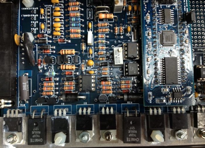
well that was interesting , put on 3.35 ohms of resistance per channel , instead of 2.35 ohms , and put in the new 127 and 42 chips ,


oh in case anyone reading this feels unsure of if they have a bad chip..


the bit of "chipnell" missing from the face is a good clue .*wink*


STARTED UP ! just fine , once i remembered to put the vac hose on, it even ticked over and had normal behaviour , went for a drive , put max demand on it by revving it on full boost , all going fine , then realised , anything above 4700 rpm was super lean cutting out territory , so maybe i can map that out , or maybe they are now so slow there is not time to feed in the fuel , time will tell... but hey , i have a working car .


Edited by robert on 31st May, 2019.

Medusa + injection = too much torque for the dyno ..https://youtu.be/qg5o0_tJxYM


evolotion

User Avatar

2909 Posts
Member #: 83
Post Whore

Glasgow, Scotland

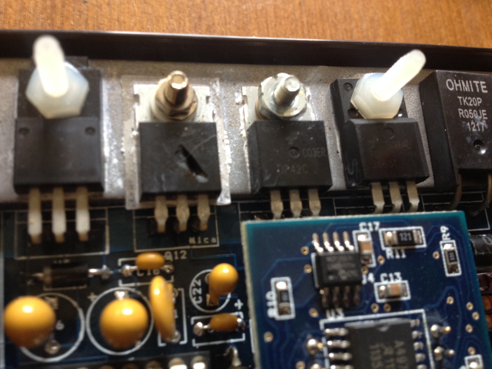
id still scope it, now its running and stable, and see where optimizations can be made. Q12 is part of the flyback dampig circuit, perhaps a reverse biased mahoosive diode per injector at the injector end of the loom may be your ticket here. but itll all show up on a scope :)

turbo 16v k-series 11.9@118.9 :)

Denis O'Brien.


robert

User Avatar

6743 Posts
Member #: 828
Post Whore

uranus

thanks DEnis , good to have some corroboration , how would i use the scope in this situation ?

Edited by robert on 1st Jun, 2019.

Medusa + injection = too much torque for the dyno ..https://youtu.be/qg5o0_tJxYM


evolotion

User Avatar

2909 Posts
Member #: 83
Post Whore

Glasgow, Scotland

had a few beers so forgive minor errors, for both these tests youll need the scope to be galvanically insulated from the car, so, if its mains powered dont have the car on a charger :) to scope current just put the probe and its ground lead to either side of your shunt resistor, using ohms law you can work out current drawn by the voltage shown on the scope and the known resistance value. If you have access to a "low amp clamp" thats another way to go which maintains galvanic isolation so you can have the car on a charger.

for the voltage, ideally check teh back EMF with a peak recording digital meter first, if its over the voltage your scope is happy with then you proably dont want to burn your scope up that said i know you have a scope capable of testing ignition coils so you should be golden lol obv your looking for the peak of the big spike after the injector shuts off. both this and the current need compared to the datasheet for Q9, Q12, Q10 and Q13 and see how close you are to maximums

turbo 16v k-series 11.9@118.9 :)

Denis O'Brien.


evolotion

User Avatar

2909 Posts
Member #: 83
Post Whore

Glasgow, Scotland

also Q12, you have a metal screw, i see a washer under it but I would swap it out for a nylon screw if you can, hell, swap it for the nylon screw on the left. the washer shoudl be plenty as it should only be +12v potential but why risk it.

turbo 16v k-series 11.9@118.9 :)

Denis O'Brien.

Home > Show Us Yours! > astra 1.4 8valve lpg turbo.
Users viewing this thread: none. (+ 1 Guests) <- Prev   Next ->
To post messages you must be logged in!
Username: Password:
Page: