Donations towards server fund so far this month.

 
£0.00 / £100.00 per month
Page:
Home > Show Us Yours! > Project "Marginal gains..."

MarkGTT

User Avatar

3249 Posts
Member #: 1194
Post Whore

Shropshire.


On 17th Jun, 2013 Aubrey_Boy said:
Hi Mark,

The cultural oasis that is Walsall *happy*...

Pretty well evenly spaced between M6 J7 & J10


Yeah just up the road from a few members on here then :)

Would love to pop over at some point and see the build.


Aubrey_Boy

User Avatar

690 Posts
Member #: 9962
Post Whore

Hi Kean / Mark,

Yes no problem, when it's at a stage where there is something to actually see by all means pop over, it just looks like a typical mini in need of restoration at the moment. Maybe when I have the wishbones done and can fit the suspension

Kean,

I'll probably decline if it's all the same *happy* I'm all welded out, maybe when all this is a distant memory

Cheers


nala56

User Avatar

825 Posts
Member #: 9661
Post Whore

Sheffield South Yorkshire GB.

A lot of really neat welding and sheet metal work there mate, nice and rewarding when you start seeing the results of your hard work, well done. Alan

Main Build
http://www.turbominis.co.uk/forums/index.php?p=vt&tid=489133

Upgrade to Turbo
http://www.turbominis.co.uk/forums/index.p...tid=448367&fr=0


Aubrey_Boy

User Avatar

690 Posts
Member #: 9962
Post Whore

Thanks Alan, it definitely helps when it starts to come together and resemble bits of a car again, cheers

Progress got halted last weekend when my direct drive compressor of just 4 years finally shook itself to pieces for the last time, countless bolts have come loose / sheared, pipes fractured over this time but I gave up trying to nurse it along, in order to try and get a larger belt drive compressor I really needed to get a proper electrical outlet for the garage to give both a 20A and a 32A supplies.

I think they are known as Commando or something outlets but they are the type we used at work for most of the workshop equipment,

Each one has its own isolator switch then feeding back to a 'garage type' MCB box (or whatever they are called)


The 20A is for the compressor, which has a running current draw of 14.5A but no doubt a higher 'start up' current draw - hence 20A outlet and other is for the welder, my Cebora has 4 or 5 current settings and most of the time I use it on '2' for the body panel stuff but when I try 3 (sometimes OK) but 4 never works as it trips the electrics. The plate on the front quotes 23A which I assume is the maximum draw so I guess setting 3 or above is exceeding the 13A household supply - dunno, I'm no electrician but hopefully this will help. Also I plan to use (borrow) a spot welder from a friend and he has told me he had to install a setup like this for his so it should allow me to use this as well.


The compressor


It's reasonable amount quieter but has much less vibration which I assume is partly due to the compliance added by the belt drive.

OK, enough excuses *wink*

I looked on t'internet to try and compare the relative position of the engine to the bulkhead, the only comparable reference I can find is the back of the cam belt cover to the edge of the bulkhead, here are two photos I found:


The red arrow showing the gap I am talking about, this is the gap I have:


I am not saying what I have is right or better it is just a slightly different set of compromises, it gives me:

Standard roundnose (although I did already have that)
Straight driveshafts in plan view
More room for front mounted rad without the back of the radiator being blocked directly
More room for exhaust manifold
Slightly improved weight distribution for 'handling'

What it makes worse:

Traction - 200ish kg moved back 40 - 45mm (About 1% less front weight distribution)
Inlet clearance
Rack clearance
Top wishbone to gearbox 'top hat' clearance
Top wishbone to oil pump clearance
Gear linkage clearance

Just got enough clearance I think.


I may still make the inlet runner have a slightly steeper angle to give a bit more clearance whilst maintaining the overall runner length but unsure of how much (if any) increasing the overall angle of the inlet assembly might effect power / performance as it effects the transition into the head.

Phase 2 might sort the inlet clearance issues, if it happens *wink* (pipe dream, but considering it)


It's a relatively small IHI, VF series, ball bearing, water cooled, Twin scroll, it weighs just under 8kg with the integral wastegate gubbins and would probably be best side mounted as far as packaging goes - engines are not really my thing but the reason I got this type was to try and minimise lag effects by being twin scroll and relatively 'small' - they appear to max out at around 350 - 360 Hp on 2.0L engines (I would no doubt run some way below that figure to try and get F16/18/20 gearboxes to survive a little) although I am having difficulty finding any meaningful technical information on it as it seems to be a relatively rare example and I cannot find any compressor maps for it.

Cheers

Edited by Aubrey_Boy on 17th Oct, 2017.


matty

User Avatar

8297 Posts
Member #: 408
Turbo Love Palace Fool

Aylesbury

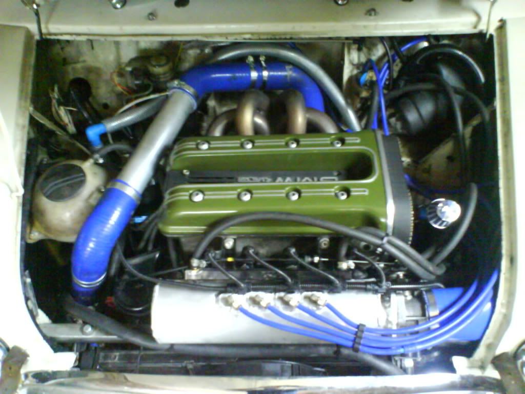
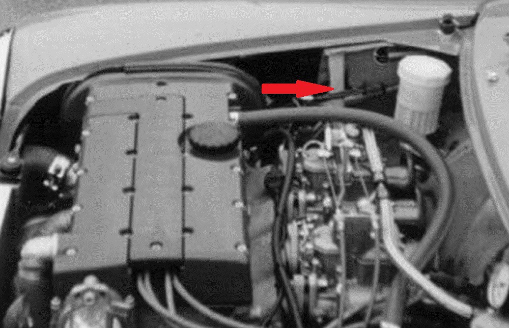
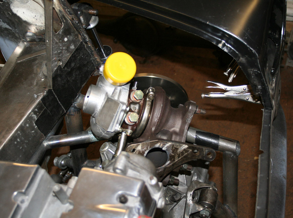
Have you thought about running a plenum chamber and using a single TB, especially if you're thinking of going down the turbo route?

It's all looking good soo far, and apart from the fettling needed, once it's done the benefits of moving it all back will definitely outweigh the cons. Keeping the standard length from end is enough of a reason. :)

https://www.facebook.com/pages/Fusion-Fabri..._homepage_panel

www.fusionfabs.co.uk


1/4mile in 13.2sec @ 111 terminal on 15psi


Adam_R

603 Posts
Member #: 1938
Post Whore

near Dundee

could you not make a bit of an indent into the panel to aid clearance a bit better like what you have done for the wiper motor


Aubrey_Boy

User Avatar

690 Posts
Member #: 9962
Post Whore

Hi Matty,

Thanks for your comments, firstly I agree totally, like you and for me it being a standard length and 'bulge' free mini was absolutely my first priority whatever the technical compromise.

I have toyed with, and may yet make a single TB version with a plenum and map it on both configurations to establish the difference but yes if I went the turbo route I would run it with a single TB.

Hi Adam,

Not sure what you mean by the wiper motor indent? As far as putting an indent into the bulkhead for more inlet clearance, yes, sure I could cut a hole or make an indent to give more room. However I want the bulkhead to remain standard.

Cheers

Edited by Aubrey_Boy on 17th Oct, 2017.


Aubrey_Boy

User Avatar

690 Posts
Member #: 9962
Post Whore

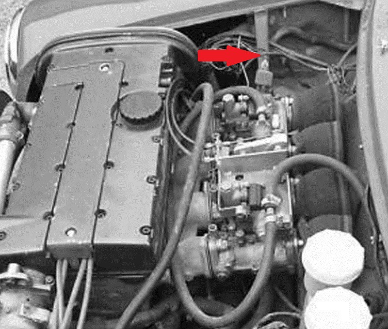
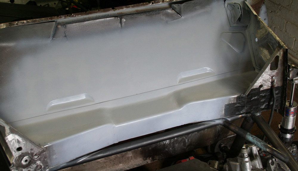
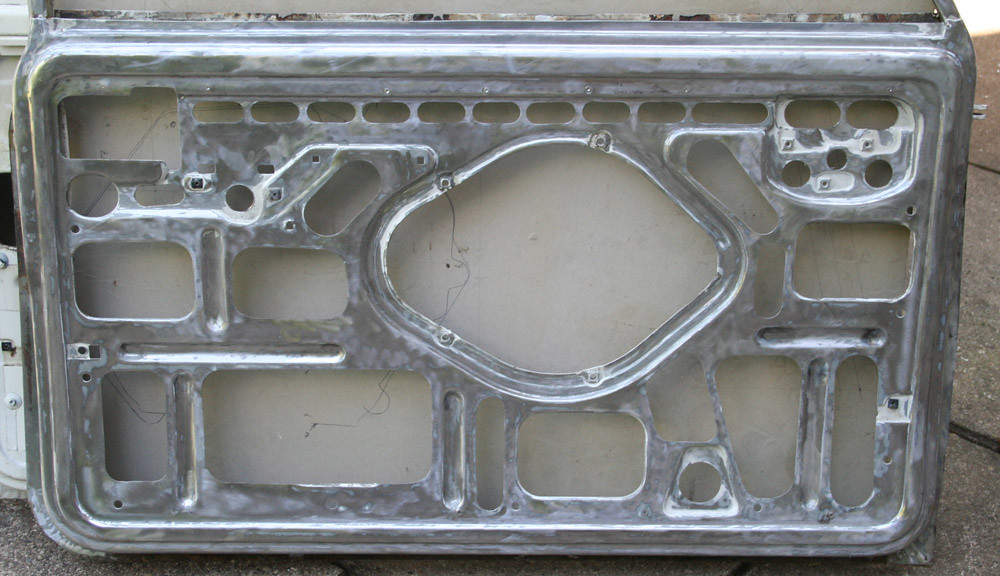
Tidied the bulkhead up a little.

I will put the normal centre bulkhead hole back in the middle, the original bulkhead was just so rippled and full of holes drilled for this and that, so I just replaced the centre section.

M Machine do a panel which puts all the centre opening detail back in so I'll order one of those as I don't think it's a panel they always have in stock.


Cheers

Edited by Aubrey_Boy on 18th Oct, 2017.


gr4h4m

User Avatar

4890 Posts
Member #: 1775
Post Whore

Chester

Looks very factory.

I run a supercharger and I don't care the TB is on the wrong side.
VEMS + 12 PSI + Liquid Intercooler = Small Bore FUN!


Aubrey_Boy

User Avatar

690 Posts
Member #: 9962
Post Whore

Thanks Graham, I want to keep it all as standard as possible, so I can convert back to completely standard if I want.

Cheers

Edited by Aubrey_Boy on 17th Oct, 2017.


Aubrey_Boy

User Avatar

690 Posts
Member #: 9962
Post Whore

Multitasking...

Spent a bit of time trying to set the ECU up as I can do this in the evening, indoors for a few hours without having to go through the ritual of going in the garage.

Had to upload a new profile as I previously had it setup as a turbo

The data logging capability is the main reason I wanted to use this ECU as it will log plenty of chassis sensors and not just engine related sensors


It's a Pectel SQ6 ECU, it has:

Dedicated RAM for data logging
Dual Lambda direct inputs
8 coil drivers
Sequential fuelling of up to 12 cylinders
Direct Stepper motor control
Throttle by wire
Traction / Launch control using 4 wheelspeed inputs
x4 EGT K typpe inputs when used with the PI dash
More analogue and Digital inputs than I know what to do with
It has the ability to act as a gearbox controller but that is not enabled on this unit

All of the inputs have the ability to take any calibration, linear or mathematical functions which means pretty well any sensor can be plugged in and data logged.

I have been using it as a bench data logger for various projects over the last few years, taking various temperature and linear potentiometer inputs for use on test rigs or various things I want to measure and/or data log

Cheers

Edited by Aubrey_Boy on 15th Jul, 2017.


Sam

1391 Posts
Member #: 1686
Post Whore

Oxford

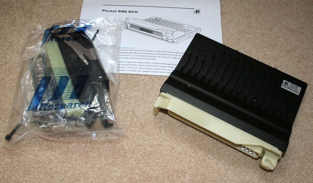
Those Pectal ECU`s are nice bits of kit. A local company to me are building up an EVO to run in some time attack series. They have bought the MQ12. They passed it to me and said don't drop it. Its worth 5k.

On 19th Feb, 2011 Miniwilliams said:
OMG Robert that's a big one


Aubrey_Boy

User Avatar

690 Posts
Member #: 9962
Post Whore

Yes we used to use the MQ12 on the Astons, I've always thought of them as being used mainly on multi cylinder engines or very high revving (20,000+ rpm) units but I'm sure it will be equally at home on the Evo.

You can get a second hand MQ12 for £4000-5000, but new I think they are over £7000 now

Cheers


Sam

1391 Posts
Member #: 1686
Post Whore

Oxford

I suspect its something to do with the number of inputs it can take.

On 19th Feb, 2011 Miniwilliams said:
OMG Robert that's a big one


Jimster
Site Admin

User Avatar

9401 Posts
Member #: 58
455bhp per ton
12 sec 1/4 mile road legal mini

Sunny Bridgend, South Wales

looking really impressive.

Team www.sheepspeed.com Racing

On 15th May, 2009 TurboDave said:

I think the welsh one has it right!


1st to provide running proof
of turbo twinkie in a car and first to
run a 1/4 in one!!

Is your data backed up?? directbackup.net one extra month free for all Turbo minis members, PM me for detials


Sir Yun

User Avatar

510 Posts
Member #: 1592
Smart Guy!

mainland europe near ze germans

I find your work pretty impressive and inspiring !

I think you should not be worried too much about even tilting the throttle bodies a bit (as the runners maintain the injector to port angle and that is probably something you should not upset, unless you want to spend time on that) using a short bit of long radius pipe to bring the TB's parallel to the bulkhead and use a shorter ram pipe.

That sir, is not rust, it is the progressive mass reduction system

http://aseriesmodifications.wordpress.com/


Aubrey_Boy

User Avatar

690 Posts
Member #: 9962
Post Whore

Jim,

Thank you for your comments, I have replied to your PM,

Sir Yun,

Thank you for comments,

Yes you are correct the injector is placed downstream of the point where I would angle the ITB manifold up slightly so hopefully won't be a problem, but as I mentioned thermodynamics / engines isn't my thing. A friend of mine works in engine development and basically said if I can't or don't intend to measure flow / tumble or any effects on injector flow / patterns (i.e. do it properly) then try to make the inlet path straight as it is rarely wrong to keep the path straight, but you are equally likely to be correct that a gentle radius wouldn't upset things but it's such a slight angle change (literally a couple of degrees) I am happy to live dangerously *happy*

To be honest I am also now getting close to the bonnet / scuttle if I try to angle it up much more so any change will be slight as I am nearly equi-spaced between the bulkhead and the scuttle, the only way to get more airbox clearance is to make the runner shorter which I would rather not do.

Cheers

Edited by Aubrey_Boy on 9th Jul, 2013.


Sir Yun

User Avatar

510 Posts
Member #: 1592
Smart Guy!

mainland europe near ze germans

I knew I had seen a solution somewhere :)

bmw s54 intakes..


Attachments:

That sir, is not rust, it is the progressive mass reduction system

http://aseriesmodifications.wordpress.com/


robert

User Avatar

6744 Posts
Member #: 828
Post Whore

uranus

Bung me the numbers off your turbo and ill see if I have a map.
ps go turbo now and save a lot of time ,as matt says .

Edited by robert on 18th Oct, 2017.

Medusa + injection = too much torque for the dyno ..https://youtu.be/qg5o0_tJxYM


Aubrey_Boy

User Avatar

690 Posts
Member #: 9962
Post Whore

Hi Sir Yun,

Thanks for taking the time to look these up, They look err, expensive and tricky to replicate *wink* But yes if they just bolted on then those darn Germans with their M3 trickery would be just the job :) , strange they all seem to be moulded in white... Almost look like rapid prototype parts, but seen enough photos to show the OEM parts are indeed that colour

Hi Robert,

Thanks for your help, It is a VF twin scroll, the excerpt below is repeated about a million times on the internet when you look for any specific details...


Exclusive turbo to the S203/S204 models, this features a twin scroll design with a slightly larger compressor than the VF36/37 turbos and different turbine design (more blades). It is a roller-bearing turbo and is likely of similar size to the VF22 turbo, but with twin scroll exhaust housing for faster spool and superior top end performance due to reduced exhaust pulse interference.


The core / body, whatever you call it is a RHF5HB, but I think this is just a generic 'body' number rather than being definative description

Started lightening some of the bolt on panels, again I can easily revert back to standard if and when required


I prefer to try and use slots / triangles and square cutouts, again to look a little more subtle, especially as I am unsure if I will run any trim and hence the inner door frame will be on show.

I am currently at about 5kg saved (without any door trim), so not a massive amount

Boot lid is similar in that only the frame / inner skin can save a bit of weight


Again some attention has been paid to the lock / fittings but again not a great weight saving. The holes in the boot lid skin will be covered by the number plate again will not be visible from outside.


I have never really had much joy with glass fibre panels so I want to try and stay with steel / metal panels

Altogether it is at around 610 kg total (according to my trusty spreadsheet) but I'll reserve judgement until it is properly weighed as a whole, this is all metal panels, all std glass, grille, bumpers, heater and std rear subframe and trailing arms etc...

Still undecided about how far I will go in terms of money spent to save more weight at the rear, time an unexpected expense while probably decide for me.

Cheers


Edited by Aubrey_Boy on 17th Oct, 2017.


Sir Yun

User Avatar

510 Posts
Member #: 1592
Smart Guy!

mainland europe near ze germans

uuhm..you may have a point robert, only 150 bhp..you'd struggle at the slightest of gradients. *hehe!*


But as it will be a squeeze to get it in as neatly as you have done so far, you will have to rebuild the whole thing again from scratch if you want to go turbo later..

Edited by Sir Yun on 9th Jul, 2013.

That sir, is not rust, it is the progressive mass reduction system

http://aseriesmodifications.wordpress.com/


Aubrey_Boy

User Avatar

690 Posts
Member #: 9962
Post Whore

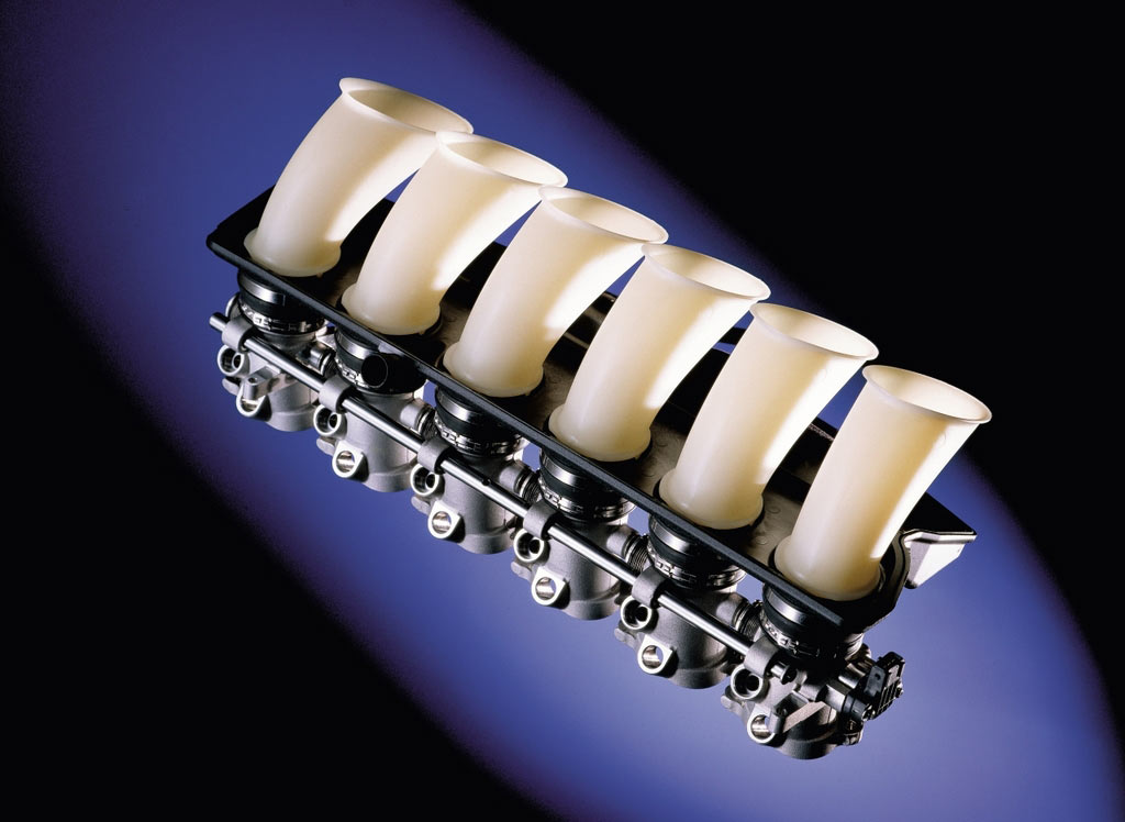
Surely with these ITB thingys and...

The BMC green engine paint (I have had about 5 years now) it must be pushing 155 bhp - green is fastest right? *happy*

Edited by Aubrey_Boy on 9th Jul, 2013.


robert

User Avatar

6744 Posts
Member #: 828
Post Whore

uranus

im guessing at a 45 to 48mm compressor wheel diameter from the bhp ?

if you can measure the big and little sizes
of the wheels I can compare to my ihi maps for you .

Medusa + injection = too much torque for the dyno ..https://youtu.be/qg5o0_tJxYM


Paul R

User Avatar

4018 Posts
Member #: 1757
Back to Fucking Tool status

Swindon

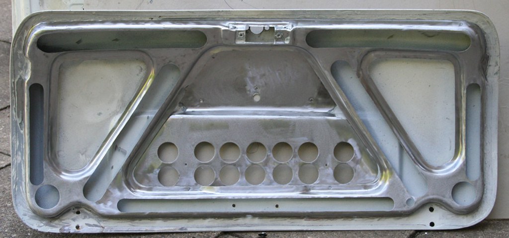
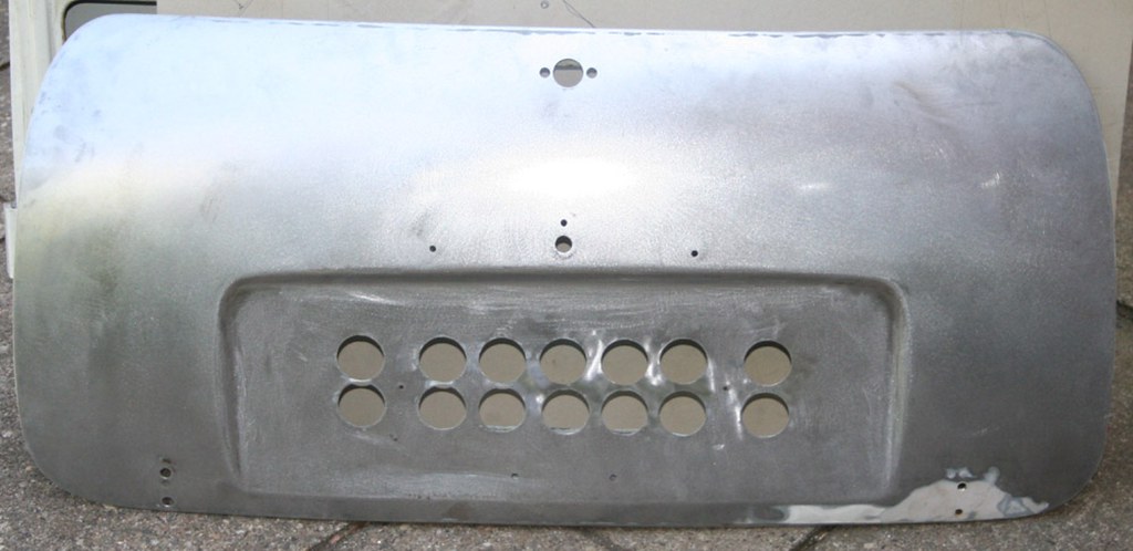
You rat scallion, I thought I was the first to do drilling/cutting out behind the number plate lol. I have started this on my metro just not finished it yet, looking bloody fantastic.

Drives
-Ford S-max Mk2 Ecoboost
-Rover 100 VVC #2 - track project

Searching is all you need on TurboMinis


Aubrey_Boy

User Avatar

690 Posts
Member #: 9962
Post Whore

Paul R,

I know what you mean, but we are all just repeating stuff done 'umpteen' times before, well I am at least *happy*, thanks for your comments tho

Robert,

These hair dryer things are a bit scarey, I tried to undo a few bolts when I was trying to 'time' the cold to hot sides in order to try and get things pointing where they needed to be, so.... I can measure the ID which feeds / exits the compressor / turbine - not sure how much help that will be...

The cold side:

ID starts around 49.5mm, then tapers down to about 47.0mm before it expands (or maybe stays parallel - not sure - feels like it expands slightly) again to the compressor

The hot side:

ID starts around 58.0mm, then tapers down to about 48.0mm where it stays parallel to the turbine

Hopefully this is of some use? Otherwise I will have to open it up further which usually results in something getting broken or damaged and those wheels look fragile *happy*

Cheers

Edited by Aubrey_Boy on 9th Jul, 2013.

Home > Show Us Yours! > Project "Marginal gains..."
Users viewing this thread: none. (+ 1 Guests) <- Prev   Next ->
To post messages you must be logged in!
Username: Password:
Page: