|
Home > Show Us Yours! > Project "Marginal gains..."
|
robert

6744 Posts
Member #: 828
Post Whore
uranus
|
|
that's ok, I can say that its around 47mm tip to tip on the comp wheel smaller diameter ,and 48mm on the turbine wheel smaller diameter ? I will have a look and see if I have a map to suit those measurements . I read that that comp wheel seems to have a lot of blades ,can you count them on the inlet side . or even better take a picky . this lets me estimate the maps height and width .
regards
Robert
ahhh found one ..

that's a very interesting wheel , no intermediaries that I can see ,and curving leading edge in a big way .
Edited by robert on 18th Oct, 2017.
Medusa + injection = too much torque for the dyno ..https://youtu.be/qg5o0_tJxYM
|
robert
6744 Posts
Member #: 828
Post Whore
uranus
|
|
righty ho ,well after a bit of a think and hunt around , a vf22 is the closest map I can find .. one source says 47.2mm inducer ,but the part no suggests a 48.5mm inducer(which I would tend to believe.)..but a straight edge bladed wheel .

i would say this should be similar but a curved blade vf42 would be a little more efficient .. my maps I have here are the rhb range so a bit different on the blade count and so on .
Edited by robert on 10th Jul, 2013.
Medusa + injection = too much torque for the dyno ..https://youtu.be/qg5o0_tJxYM
|
Aubrey_Boy

690 Posts
Member #: 9962
Post Whore
|
|
Hi Robert,
Thanks for taking the time to look at this, I have that VF22 map but wasn't sure how applicable it would be as I don't have a feel for the relative sensitivities of the different parameters like wheel diameter, the fact that VF22 is non twin scroll etc so wasn't sure if it was a good enough start point
Lots of information / comments that I have found (on the internet - so they must be true - right  ) are often contradictory as relatively few people seem to have used one of these ) are often contradictory as relatively few people seem to have used one of these
I forgot but some time ago I found the following info (not sure of the source now), which seems to fit in with the measurements I made:
Compressor:
Small dia 46.5mm
Large dia 60.0mm
12 blades
Turbine:
Small dia 48.0mm
Large dia 53.0mm
9 blades
Cheers
Edited by Aubrey_Boy on 18th Jul, 2013.
|
robert
6744 Posts
Member #: 828
Post Whore
uranus
|
|
when you say 12 blades that's 6 big blades and 6 little wimpy ones hidden in between ?
the twin scroll turbine housing wont affect the compressor map ...just if you build a nice split zorst you might get a bit more response.
Medusa + injection = too much torque for the dyno ..https://youtu.be/qg5o0_tJxYM
|
Aubrey_Boy
690 Posts
Member #: 9962
Post Whore
|
|
Yes 6 man size and 6 little snivellers...
All with the same curved leading edges
The turbine wheel is just regular straight edged all the same geometry.
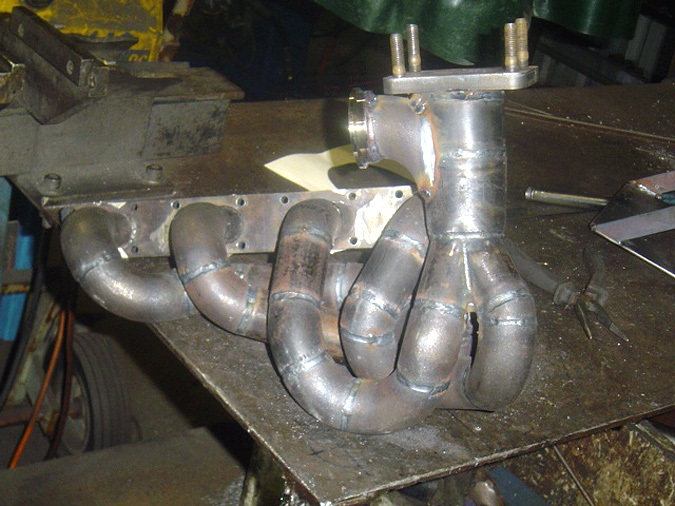
Yes, if Phase 2 does become Phase 1 then it will be a divided equal length manifold, if I am going to the trouble of making a specific manifold which I will have to then it might as well make the most of the twin scroll scavenging. No idea on the potential effect of longer versus short primaries (all still equal length) would have as the side mounted version would be significantly longer primaries.
Front mounted gives me a simpler turbine discharge routing at the expense of radiator positioning, it will fit behind a std grille position as I tried it there subject to being able to 'time' it suitably.
Side mounting will help with side to side weight distribution (circa 10 - 12 Kg left of the car centreline) and in theory help rad positioning but the turbine discharge will still have to head back out to the front of the car unless it can be routed down the back of the block but it is pretty congested and would almost certainly have to become oval / funky shaped section to pass through the available space.
Thanks again
|
robert
6744 Posts
Member #: 828
Post Whore
uranus
|
|
yup , , id g front mount ,and link the pairs with the biggest gap in the firing order . eg 1/4 and 3/2 for maximum gross pulsage down the tubey snorkeller (as its known)
Medusa + injection = too much torque for the dyno ..https://youtu.be/qg5o0_tJxYM
|
Aubrey_Boy
690 Posts
Member #: 9962
Post Whore
|
|
Mocked up the possibility of the front mount turbo


The only bit which is relatively straight forward is the turbine discharge, the tube shown fits between the front cross member and the block


It just fits behind the grille when fitted.


I appreciate it's easy to just hang a turbo in there and think its job done but I know there is plenty more routing and packaging things that would need sorting but it seems more 'contained' and simple than the side mount option I looked at, IF I were to do it.
I have been doing some calcs based on the compressor map, need to do a bit more research before I feel like I have the slightest understanding of what it is I am doing though.
Cheers
Edited by Aubrey_Boy on 15th Jul, 2017.
|
robert
6744 Posts
Member #: 828
Post Whore
uranus
|
|
as long as your compressor has enough total flow for the bhp required ,and its in the right area boost wise , I wouldn't get to hung up on map profiles etc..
also ..don't forget too offset the weight gain with the need for less silencing .
it looks like you have lots of room.
Medusa + injection = too much torque for the dyno ..https://youtu.be/qg5o0_tJxYM
|
Aubrey_Boy
690 Posts
Member #: 9962
Post Whore
|
|
OEM wise this unit delivers 320 Hp / 422 Nm @ ?bar boost (All the OEM STi versions I can find data for use no more than 1 bar) in a 2L 4cyl road car, so I assume it does this reliably...
Tuned / increased boost they seem to be about 350 - 360 Hp for the same car
Doing the standard calcs to have a quick look - see:
'Target' Hp = 300 (Target for the purpose of these calcs)
AFR = 12 - (Internet value)
BSFC = 0.55 - (Internet value)
Equates to about 33.0 lbs/min as a Mass flow rate
Depending on how you choose to turn this into a volumetric rate
431.5 CFM, just using a 'std' value for air density (I know no such thing as a std density for air)
476.8 CFM, using Ideal gas laws and some normalised / standardised conditions
The VF22 seems to max out at about 490 CFM / 2.7 pressure ratio
Then using even more assumed values for VE, Inlet depression, losses between compressor and inlet etc...
I get a Pressure ratio of around 2.35
Which puts you right near the choke line at max revs and don't get to the surge line until about 3000 - 3500 RPM (staying at 2.35 pressure ratio).
Also if you try and push it to 350 - 360 Hp you can see that you start to get outside of the operating range of this unit - which seems to agree with the real world figures people are quoting
I know lots of estimated values but all seems sensible enough to suggest it will be OK, (which was really already known as it is fitted to 2.0L / 4 cyl / 16v OEM road cars that produce 320 Hp with OEM reliability)
I agree I won't get too hung up on this stuff just more for interest than likely to influence what I do as I will have to package everything in the space available (without having anything obvious visible - is the plan) which will no doubt worsen some of the assumed efficiencies / losses.
I guess just a single rear silencer then say 4 - 5" OD say 450mm long and do away with the planned intermediate box.
It only looks like lots of room because it's empty
Cheers and thanks again
Edit: Added Compressor map (Ignore the black map below, the green map is the one being considered)

Edited by Aubrey_Boy on 15th Jul, 2017.
|
theoneeyedlizard
7263 Posts
Member #: 1268
The Boom Boom speaker Police!
Essex
|
|
This has suddenly become much more exciting!
I for one would love to see this car boosted.
In the 13's at last!.. Just
|
Paul R

4018 Posts
Member #: 1757
Back to Fucking Tool status
Swindon
|
|
I would personally mount the turbo above the gearbox, gives more room for rad/ic/ccrad still have the down pipe out the same place?
Drives
-Ford S-max Mk2 Ecoboost
-Rover 100 VVC #2 - track project
Searching is all you need on TurboMinis
|
Aubrey_Boy
690 Posts
Member #: 9962
Post Whore
|
|
Paul,
I still haven't decided (assuming I do add a rotary silencer) between front and side mount...
This shows the front mount behind a std front grille.

My plan was to look at side mount today just to compare with what I did yesterday
I agree that leaving all / any available space at the front for both the engine water cooling heat exchanger and the possibilty of an intercooler makes sense due to the available airflow.

So, similar to previous photos here is the side mount position... It is difficult to see whats going on though without any pipe work showing where things are going...
I really like that it is weight added to the passenger side, also that if things are done correctly I still have space up front.
This is the sort of route which would be taken if I try to make the turbine discharge exit go down the back of the block (looks like a good way to heat the inlet manifold up )

But I cannot question the room this gives me in front of the block if the primaries don't eat this space up for rads and IC's

Another photo of the side mount option, I visualise the inlet air filter being in the inner wheel arch as an airbox or something similar...


A new steel rear parcel shelf as the old one had the usual extra holes cut in to it.
Cheers
Edited by Aubrey_Boy on 17th Oct, 2017.
|
Sir Yun

510 Posts
Member #: 1592
Smart Guy!
mainland europe near ze germans
|
|
I'd wager a guess that by the time you have a decent manifold going to the side, the entire front will be full of very hot primary pipes. So the IC will have some efficiency problems as well if it's anywhere near. if you want to use water foggers on the IC it will probably start to steam like a locomotive :)
All the OEM's use a short manifolds because it minimizes pulse energy loss and they have fck all space to work with as well. I very much doubt (based on what I have read on the subject) that a tuned manifold will do one bit better regardless of the space needed.
if you have the lift hand side ''free'' for the IC and rad (that will probably have to be custom made anyway) you have at least one corner that is a tad less hot.
Air intake in the inner wing is prone to ingesting water when it gets wet.. it is charge cooling but not very controlled I reckon. :)
That sir, is not rust, it is the progressive mass reduction system
http://aseriesmodifications.wordpress.com/
|
MarkLD
22 Posts
Member #: 606
Member
|
|
Hi Spencer
Good to see you are making progress, all to an excellent standard as usual.
Looks like you are going through the same thought process i did when looking at adding a turbo. I couldn't get it to work within my constraints so went for a rear mounted turbo setup which has worked very well.
If you would like to come round and have a look at my car to help towards making your decision then give me a shout.
Cheers
Mark
|
Paul R
4018 Posts
Member #: 1757
Back to Fucking Tool status
Swindon
|
|
I would have said to do the side mount but tune the lengths on the side not out in front to minimisethe heat there, also would have the exhaust entery from gearbox up into the turbo to create abit more room as the twin screw has quite a large flange
Like this
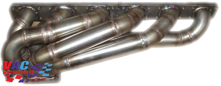
Edited by Paul R on 15th Jul, 2013.
Drives
-Ford S-max Mk2 Ecoboost
-Rover 100 VVC #2 - track project
Searching is all you need on TurboMinis
|
Aubrey_Boy
690 Posts
Member #: 9962
Post Whore
|
|
Hi Sir Yun,
I agree with everything you mention as I have been pondering / mocking up these same issues.
For me the 3 main concerns regarding fitting a turbo are: (Well to this car anyway...)
Packaging (By this I mean do the parts even physically fit let alone do so properly / efficiently) - Without anything obvious on show.
Heat Management
Gearbox torque capacity
'Packaging' was more straight forward than I thought as I didn't think front mount would fit at all, but I think with the engine being further back and the choice of turbo must have lumps and bumps in the right places to allow it to fit tightly to the block.
Heat - The direct heat soak from the turbo and exhaust and being water cooled the additional loading on the cooling system. And if an IC were fitted then the fact that the available airflow would need to be shared between rad and IC makes things more difficult.
As far as the primaries go I agree and I mentioned this to Robert in an earlier post that whilst in theory the side mount gets the turbo out of the way the fact that you have to feed it with primaries and have the turbine discharge routed back to the front of the car you can quickly end up with the same problems through radiated heat and the 'blockage' these pipes would create behind any heat exchanger. Keeping the primaries high up helps and might be enough to minimise the blockage, my heath robinson image below maybe shows better what I mean but the exhaust return below them will create a blockage to any rad. I think I could contain the primaries in the area shown but it would end up an expensive exercise if it didn't work out probably need to play with some flexi ducting to be sure first.

When you say 'tuned' manifold, do you mean overall length i.e. short vs long, I agree I have no data to that could help me choose one over the other so everything else being equal it might as well be short. As far as equal primaries go I would still choose this within what could be sensibly achieved / packaged.
Charge cooling was / maybe still is what I thought would be the most likely due to lack of space, but I know little about it other than it looks expensive.
If the airbox / filter ends up in the inner arch I agree and had already planned a fully or partially lined inner arch to try and protect from dirt and water whilst still allowing air in...
All of this is why I had always made the potential turboing option 'phase 2', because if the N/A already is marginal as far as say heat management goes then a likely no no, the problem with doing it as a phase 2 is all the additional expense of redoing stuff / pistons, manifolds, repackaging etc...
Incidentally how do the A series turbo cars fair for heat problems etc as they tend to have turbos fitted in an area with limited air flow as far as general under bonnet temps, I know there is one current thread discussing heat problems
Cheers
Edited by Aubrey_Boy on 15th Jul, 2017.
|
theoneeyedlizard
7263 Posts
Member #: 1268
The Boom Boom speaker Police!
Essex
|
|
32 deg ambient on Saturday when I took a friend out for a drive using all available bananas.
My car is very tight for space under the bonnet (large front mounted intercooler and associated pipework blocking the grille area, brake servo, full inner wings etc). The only additional considerations of cooling are two sets of louvres in the bonnet.
Water temp didn't rise above 90deg even when sat in traffic.
In the 13's at last!.. Just
|
Aubrey_Boy
690 Posts
Member #: 9962
Post Whore
|
|
Hi Paul,
The images don't do a great job of showing how much / little space there is, but the primaries would have to stay 'high' to leave space below for heat exchangers.
The red area is where the twisty/ curvy bits of the primaries would need to be contained whilst still clearing the bonnet, the turbine discharge pipe then would sit below this so create a blockage to airflow.

The area in front of the gearbox is not a space which can be used as this would result in being tight against any rad.
So basically I think the primaries pretty well have to stay above the bonnet to grille shut line as far as I can see to leave space below
It does look like a recipe for this area to end up raging hot though, I suspect the bonnet might be a bit hot if you try and open it
On the bright side it does make the phase 1 N/A route seem pretty straight forward
I think I would need to start and see what size heat exchangers could be packaged and how badly they are shrouded and what if any path the air flow has to exit the rads
Hi Mark,
Thanks for your comments
As discussed will catch up soon, hopefully see how well your turbo goes
Cheers
Edited by Aubrey_Boy on 15th Jul, 2017.
|
Aubrey_Boy
690 Posts
Member #: 9962
Post Whore
|
|
Thanks Mr Lizard 
That's useful info, I guess the biggest difference would be the physical surface area of associated exhaust pipe work living under the bonnet for my side mount
I'll have a look to see if I can find a build diary / photos of your install
I need to start mocking up some rads / IC's
Cheers
|
theoneeyedlizard
7263 Posts
Member #: 1268
The Boom Boom speaker Police!
Essex
|
|
http://www.turbominis.co.uk/forums/index.p...d=191396&fr=325
In the 13's at last!.. Just
|
TurboDave16V
Forum Mod
10979 Posts
Member #: 17
***16***
SouthPark, Colorado
|
|
I have the same turbo - mine originated from a JDM 2.5 legacy IIRC. Never could figure out exactly which map it was akin to, because it never fitted into all the criteria for blades and wheels sizes.
I believe the IHI compressor wheels have a 6.2mm (or perhaps 6.5mm) ID , so if you like the twin scroll performance, but dicover the compressor is a little off, it would be relativly easy to mate the GT-series compressor wheels (which there are a lot of maps for) and housings to the IHI unit. Only reason I personally didn't pursue this, is that I understand these IHI BB units are not as well suited to the higher boost levels as the Garrett range.
On 17th Nov, 2014 Tom Fenton said:
Sorry to say My Herpes are no better
Ready to feel Ancient ??? This is 26 years old as of 2022 https://youtu.be/YQQokcoOzeY
|
Aubrey_Boy
690 Posts
Member #: 9962
Post Whore
|
|
Cheers I had found your build diary and see what you mean about the FMIC
Hi Dave,
I think that it only came on the JDM S203 / S204 STi variants of the Impreza, but as I say engines aren't really my thing so probably wrong, just the thermal issues which are my main concern and not sure I can answer any of them satisfactorily
Cheers
Edited by Aubrey_Boy on 19th Jul, 2013.
|
Sir Yun
510 Posts
Member #: 1592
Smart Guy!
mainland europe near ze germans
|
|
On 17th Jul, 2013 Aubrey_Boy said:
Hi Sir Yun,
When you say 'tuned' manifold, do you mean overall length i.e. short vs long, I agree I have no data to that could help me choose one over the other so everything else being equal it might as well be short. As far as equal primaries go I would still choose this within what could be sensibly achieved / packaged.
Cheers
I am no expert ! But I have researched this stuff quite a bit for my ''finished in 2050 at this rate 16v conversion'' before I got sidetracked with work ( yuk) and my renewed interest in the 5 port heads.
Tuned, as tuned to a specific rpm range harmonic length, preferably equal. It used to be popular in the 80's and 90's and is still used for race/rally engines with a turbo. I would just go for fit regardless of this all, you will have way too much power anyway :) .
Maybe this is of interest. It is pretty masterful how they packaged all this stuff in that space without it melting after 5 minutes
http://www.bmwblog.com/2011/09/22/intervie...elopment-bmw-m/
That sir, is not rust, it is the progressive mass reduction system
http://aseriesmodifications.wordpress.com/
|
robert
6744 Posts
Member #: 828
Post Whore
uranus
|
|
something to bear in mind is that the chances of holding this engine on a high heat inducing engine mode ,for long periods of time are slim.the other thing is that for its size and power ,the inlet area of the engine bay is very big ,so allowing an equal area for air to get out into a low pressure area should create all the
flow you would need .
I, like joost(sir yun),would not bother with tuned lengths , just make it as compact as possible . you can look at my astra thread?
http://www.turbominis.co.uk/forums/index.php?p=vt&tid=378624
that made around 140 bhp from 6 psi on a 1400cc 8 valve engine.
Edited by robert on 17th Jul, 2013.
Medusa + injection = too much torque for the dyno ..https://youtu.be/qg5o0_tJxYM
|
Aubrey_Boy
690 Posts
Member #: 9962
Post Whore
|
|
Robert / Sir Yun,
"High heat inducing, engine mode" - I have to admit that I am probably guilty of just thinking of a turbo sitting there stinking hot the whole time and not really thought about what I would call the duty cycle of the turbo and hence its heat generation cycle.
Trying to use EGTs to give me some idea of the temperature delta between on and off boost, do you know what a typical delta would be? assuming the on / off boost of a typical 'A series installation would be in the slightest bit relevant, or just a typical off boost EGT / turbo frame temp.
Thanks for the BMW article, interesting read.
Come to think about most of the 'equal length' discussions I have had over the years have indeed been specifc to race engines (both N/A and boosted) and the trouble they go to make the equal lengths just that - volume measurement of each primary / secondary etc...
Power wise I have this figure in my head of 200 @ Wheels which should be more than enough for me to run out of talent and should be relatively easily achieved. My rationale behind a smallish turbo, twin scroll, lowish boost (to get 200 Whp), CR? equal length primaries etc... Is just to try and have fast spool and smooth power delivery therefore where possible do what enables this efficiently and a not a quest for ultimate power.
Yes definately the grille inlet area is bigger than most modern cars and moving the engine back was also to help reduce the blockage to air flow the XE lump causes and as it heavily shrouds most of the airflow exit path on the drivers side, wherever possible I will try to duct / coerce the exit flow but there are few options without creating holes in bodywork.
Had a quick look at the Astra build, looks inetersting will read through again tomorrow
Cheers
Edited by Aubrey_Boy on 18th Jul, 2013.
|
|
Home > Show Us Yours! > Project "Marginal gains..."
|
|
|
