
| Page: |
| Home > Show Us Yours! > Project "Marginal gains..." | |||||||
 690 Posts Member #: 9962 Post Whore |
23rd Nov, 2012 at 09:56:43pm
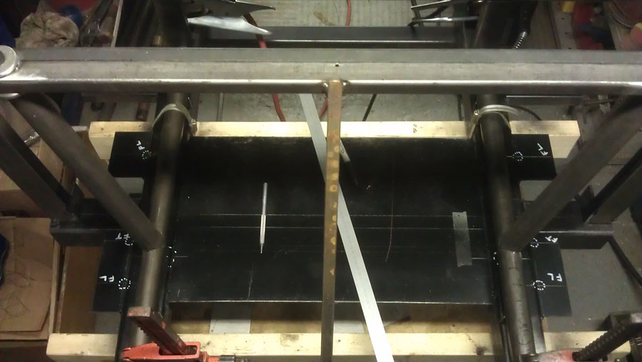
A bit more done, it's taking ages because there is so little space each time you change something you have to fully mock up everything in that area as some many things are within a few mm
Edited by Aubrey_Boy on 7th Jul, 2017. |
||||||
 5417 Posts Member #: 6181 Double hard bastard brookwood woking |
23rd Nov, 2012 at 10:02:25pm
Looks good mate. that is what put me off making a frame. making a frame to make the frame in I have started posting on Instagram also my name on there is turbomk1golf
On 1st Nov, 2007 Ben H said:
There is no such thing as 'insignificant weight saving', it all adds up. |
||||||
|
690 Posts Member #: 9962 Post Whore |
29th Nov, 2012 at 01:31:02am
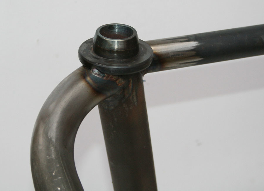
Cheers, yes even with the 'jig' it is still suprising how much things can move if you weld one area too much before welding elsewhere
Edited by Aubrey_Boy on 18th Oct, 2017. |
||||||
|
690 Posts Member #: 9962 Post Whore |
18th Dec, 2012 at 06:11:45pm
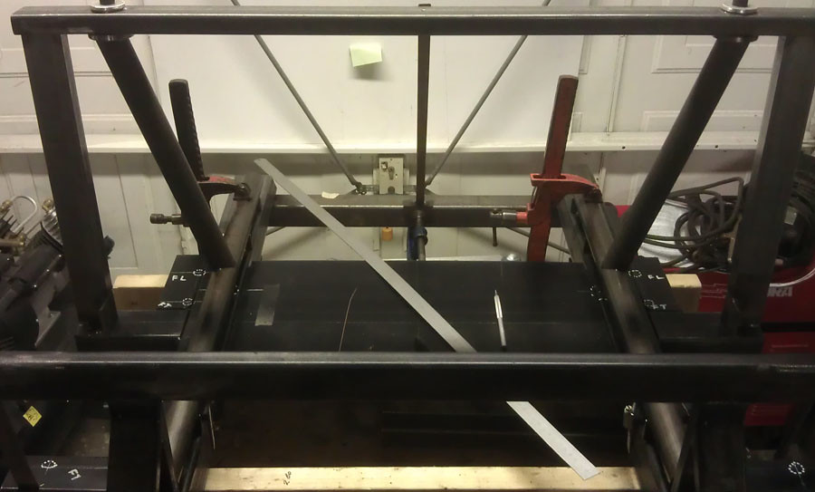
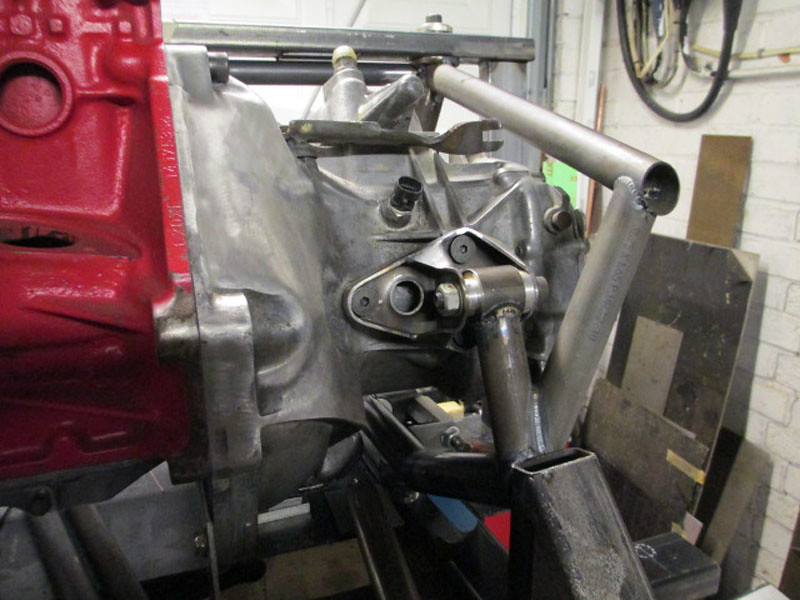
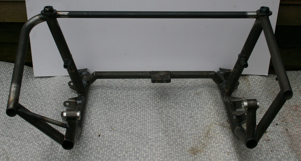
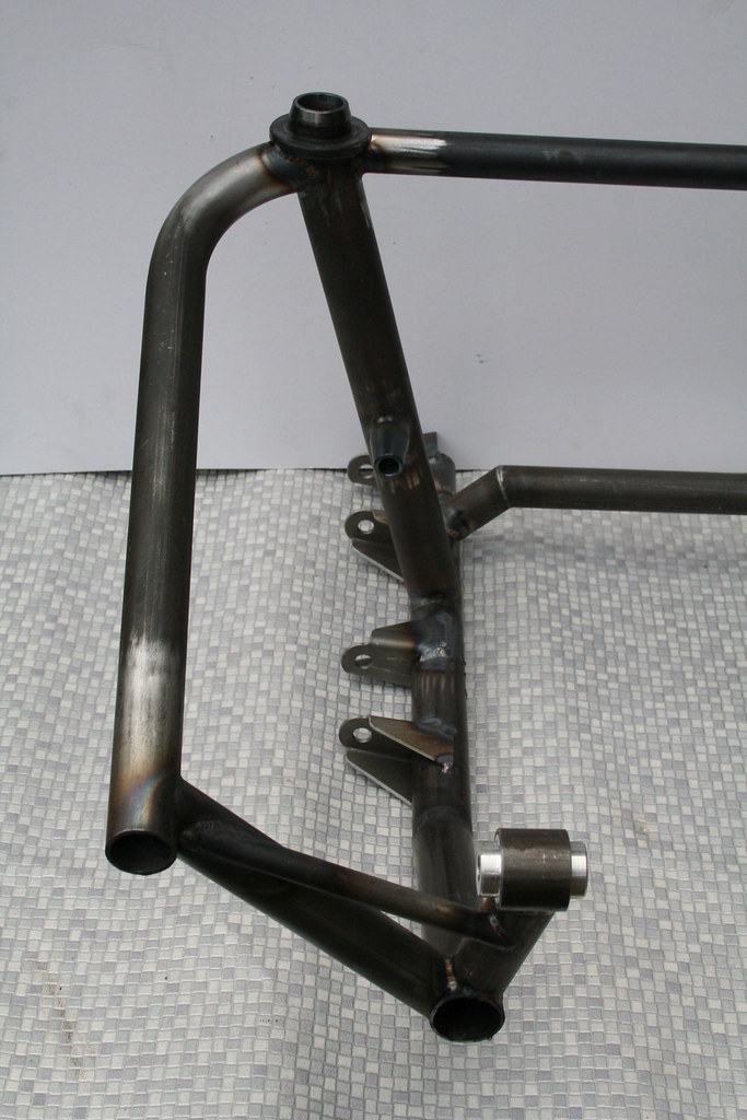
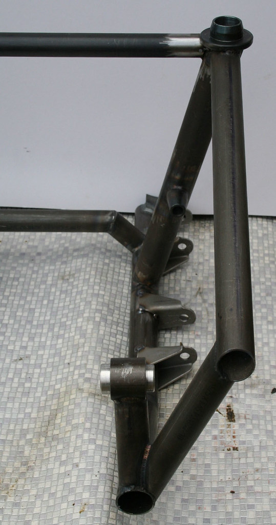
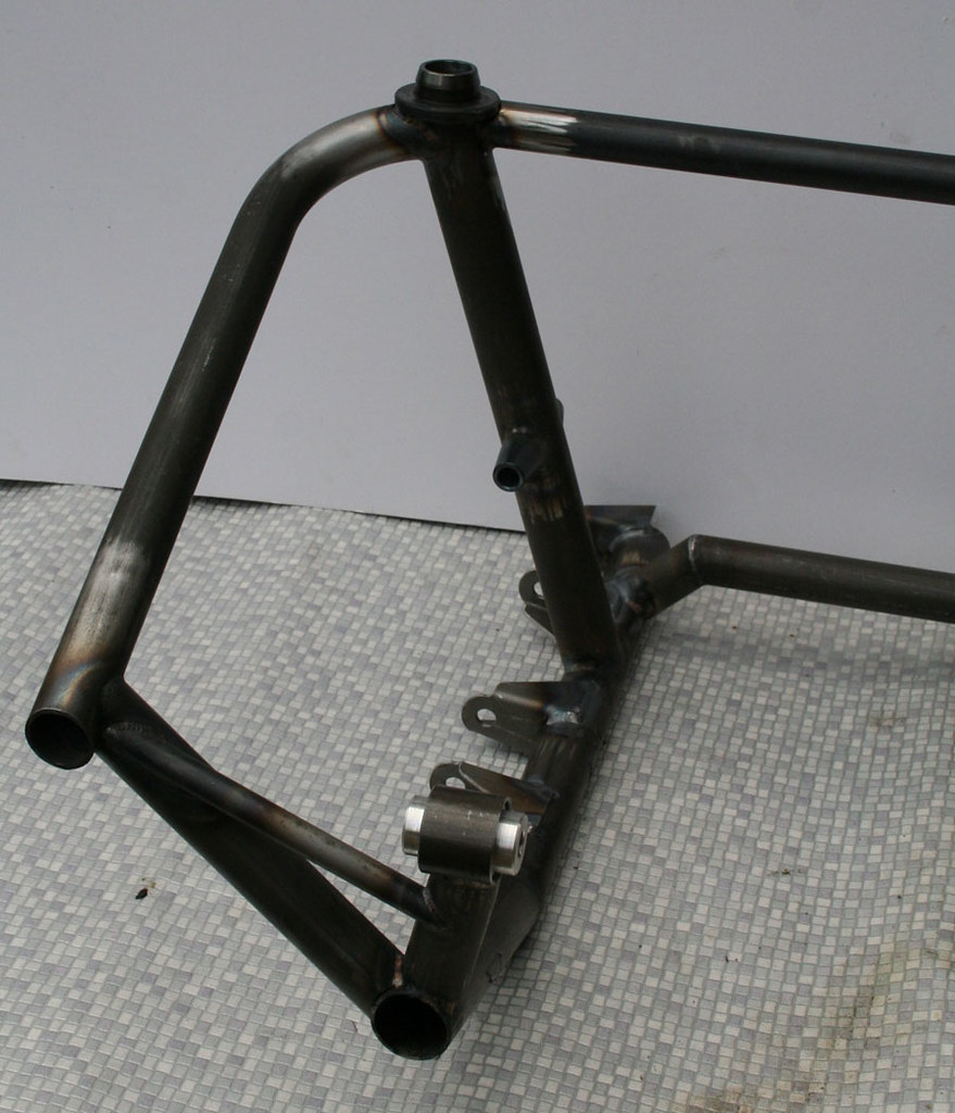
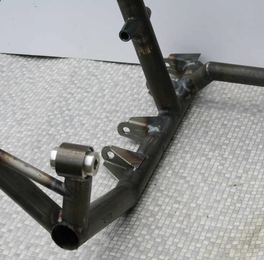
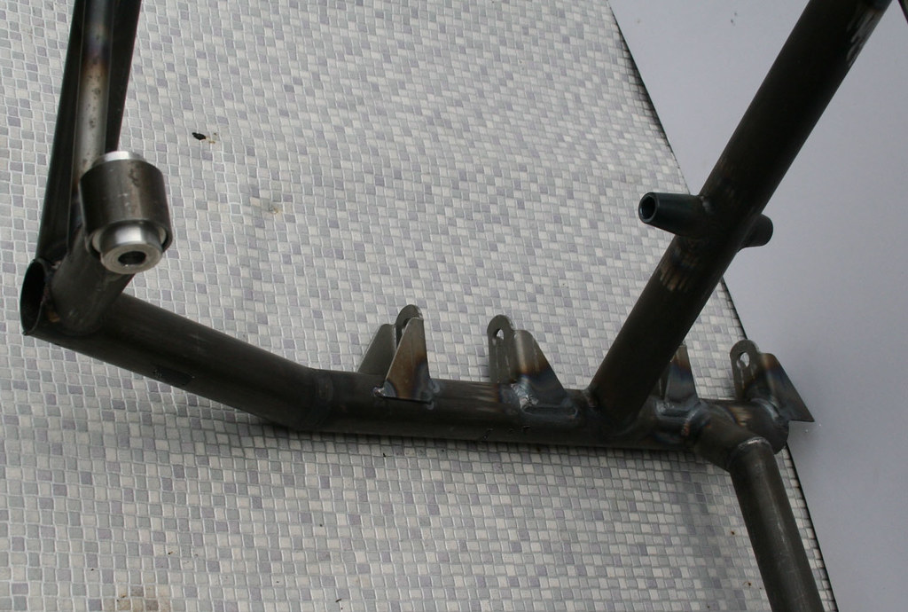
The subframe is back in the jig having the upper wishbone mounts and the steering rack / cross member tube added.
Edited by Aubrey_Boy on 18th Oct, 2017. |
||||||
 16540 Posts Member #: 4241 King Gaycharger, butt plug dealer, Sheldon Cooper and a BAC but generally a niceish fella if you dont mind a northerner Rotherham, South Yorkshire |
18th Dec, 2012 at 06:41:39pm
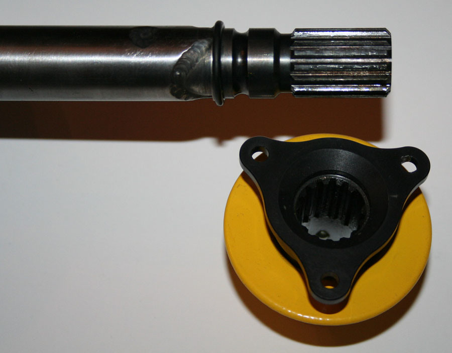
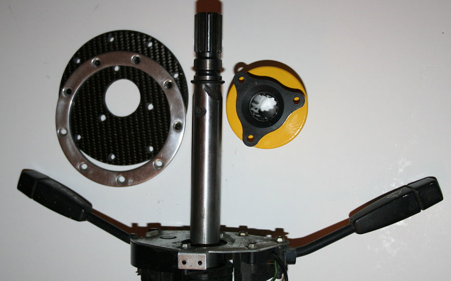
Interesting. I'm in the middle of planning how to bastardise my wheel onto one of the lower end of the market QR adaptors. I am too tall for a mini... On 11th Feb, 2015 robert said:
i tried putting soap on it , and heating it to brown , then slathered my new lube on it 
|
||||||
|
264 Posts Member #: 8853 Senior Member Bristol |
18th Dec, 2012 at 07:12:50pm
I bought a laranca one too, they're not as expensive as you think |
||||||
|
690 Posts Member #: 9962 Post Whore |
23rd Dec, 2012 at 05:49:43pm
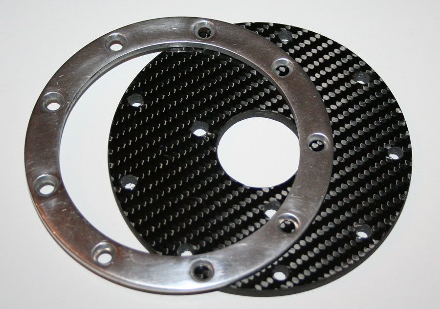
For some reason the Laranca badged QR's seem to have disappeared off the face of the earth, SPA seems to have a very similar one... But I used the single seater one as it was both the cheapest and the lightest that they did. Demon Tweeks do one which is like my Laranca one but seems to have gone from a CNC profile to a straight edged design?
Edited by Aubrey_Boy on 3rd Dec, 2014. |
||||||
|
690 Posts Member #: 9962 Post Whore |
29th Dec, 2012 at 03:34:06pm
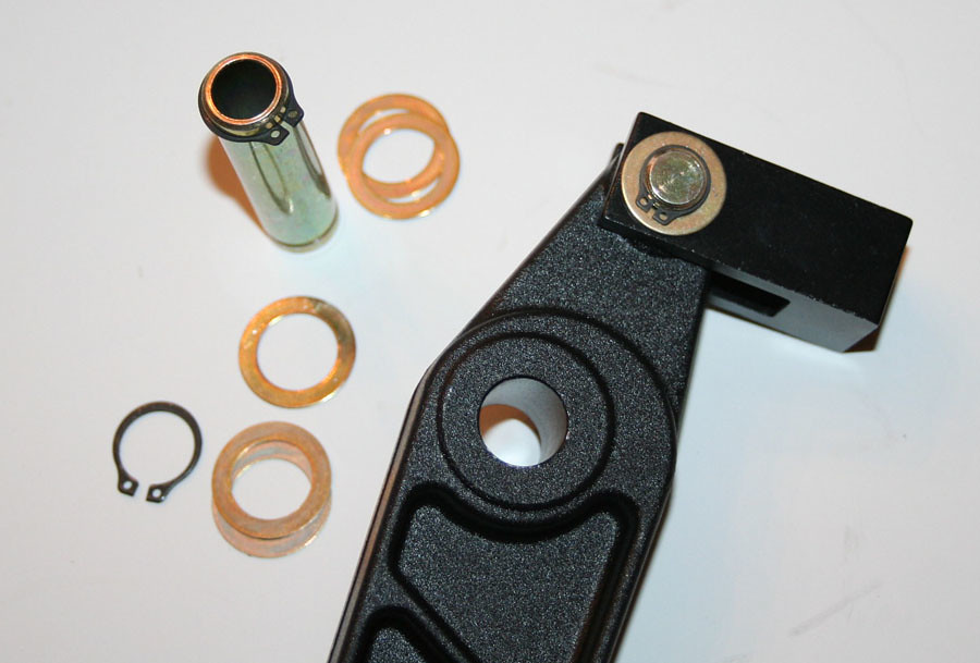
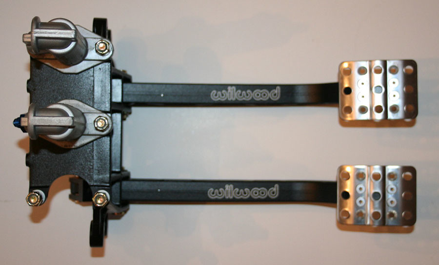
For one reason and another I am considering going with a hydraulic clutch
Edited by Aubrey_Boy on 18th Oct, 2017. |
||||||
|
690 Posts Member #: 9962 Post Whore |
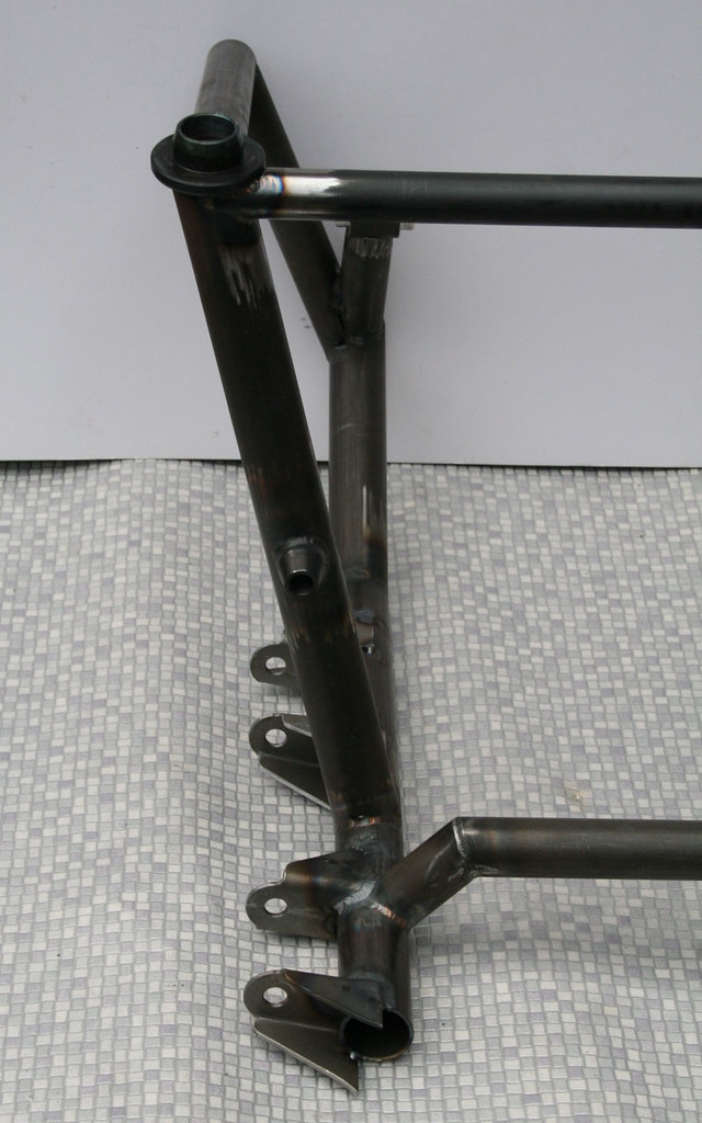
27th Jan, 2013 at 10:35:07pm
Its been a while, but the subframe is still progressing, albeit more slowly than I had hoped.
Edited by Aubrey_Boy on 7th Jul, 2017. |
||||||
 8297 Posts Member #: 408 Turbo Love Palace Fool Aylesbury |
27th Jan, 2013 at 11:18:39pm
Superb, that subframe is really starting to take shape now! https://www.facebook.com/pages/Fusion-Fabri..._homepage_panel
|
||||||
 6729 Posts Member #: 618 Post Whore Glasgow |
28th Jan, 2013 at 09:22:55am
I can't believe i've missed this thread - excellent fab work going on |
||||||
 3249 Posts Member #: 1194 Post Whore Shropshire. |
28th Jan, 2013 at 07:56:30pm
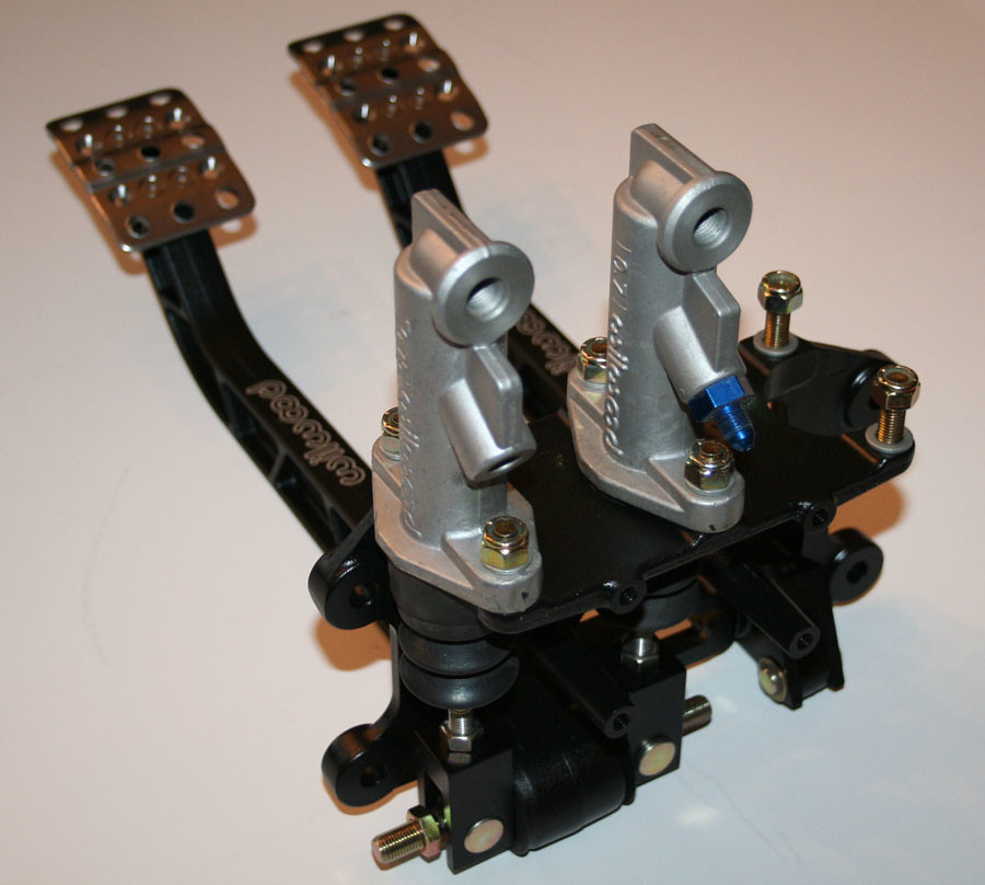
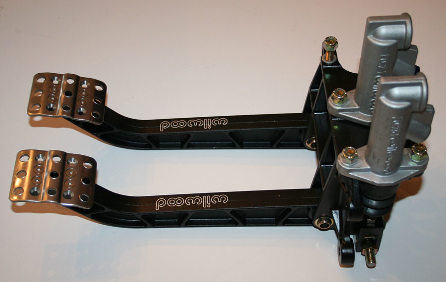
thanks for the pedal box info, im looking at buying one for my vauxhall build.
|
||||||
 3074 Posts Member #: 1348 Post Whore wakefield West Yorks |
28th Jan, 2013 at 08:54:40pm
On 28th Jan, 2013 Rob Gavin said:
I can't believe i've missed this thread - excellent fab work going on Dito 
looks awsome rick |
||||||
 4890 Posts Member #: 1775 Post Whore Chester |
28th Jan, 2013 at 10:41:53pm
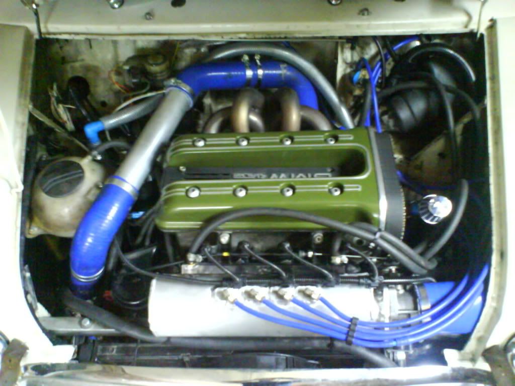
Very nice, got to love some welding action... I run a supercharger and I don't care the TB is on the wrong side.
|
||||||
|
690 Posts Member #: 9962 Post Whore |
29th Jan, 2013 at 07:43:31pm
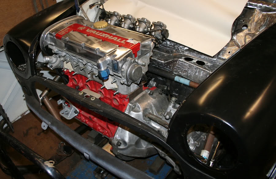
Thanks very much for the comments, hopefully by next week the subframe will be ready to trial fit in the car again - but this will just be to check engine position as I need to get the wishbones fabricated in order to do much else.
Edited by Aubrey_Boy on 18th Oct, 2017. |
||||||
|
264 Posts Member #: 8853 Senior Member Bristol |
29th Jan, 2013 at 07:48:42pm
Great work. Is the engine solid mounted or are the bushes a polymer of some sort? |
||||||
|
690 Posts Member #: 9962 Post Whore |
29th Jan, 2013 at 10:11:54pm
Hi,
Edited by Aubrey_Boy on 29th Jan, 2013. |
||||||
|
690 Posts Member #: 9962 Post Whore |
15th Feb, 2013 at 09:01:53am
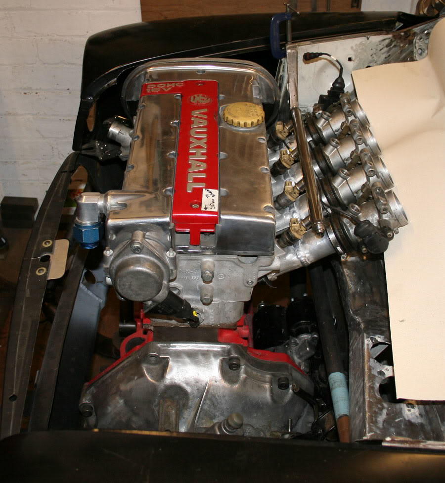
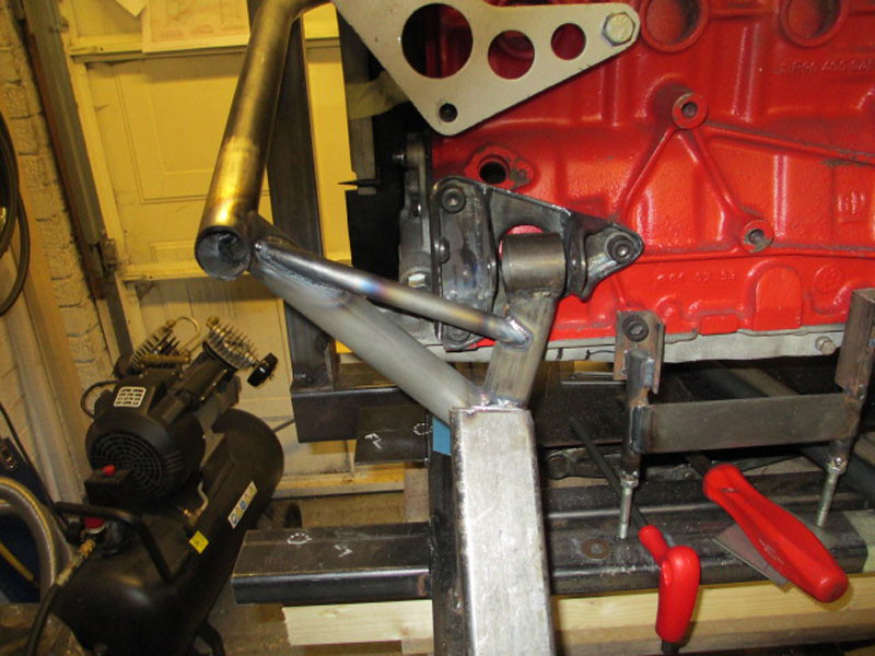
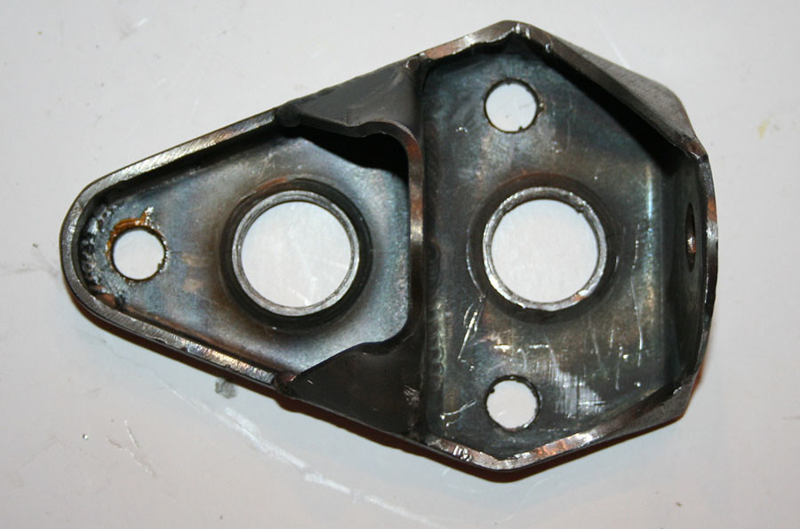
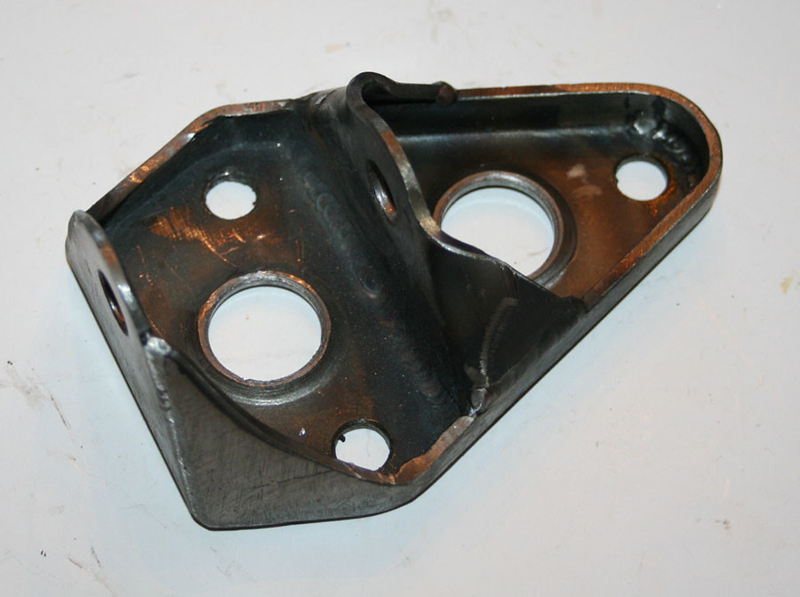
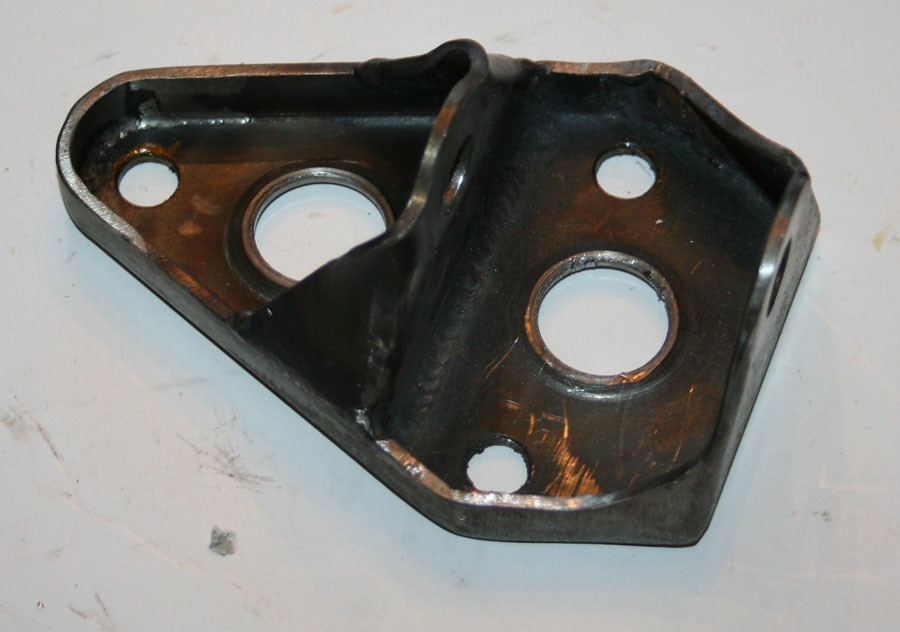
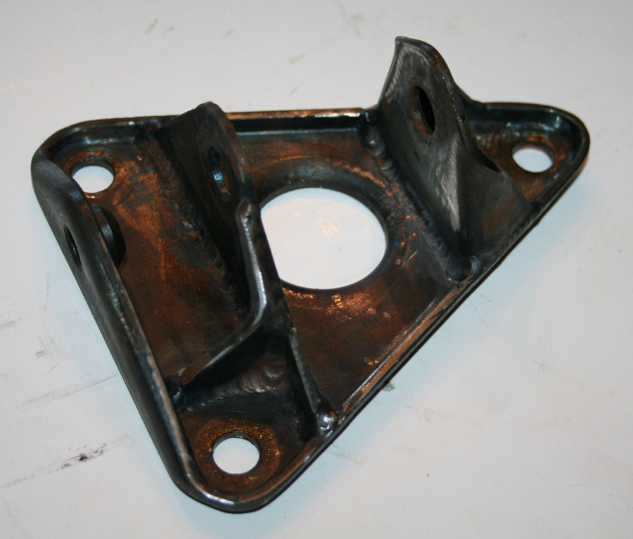
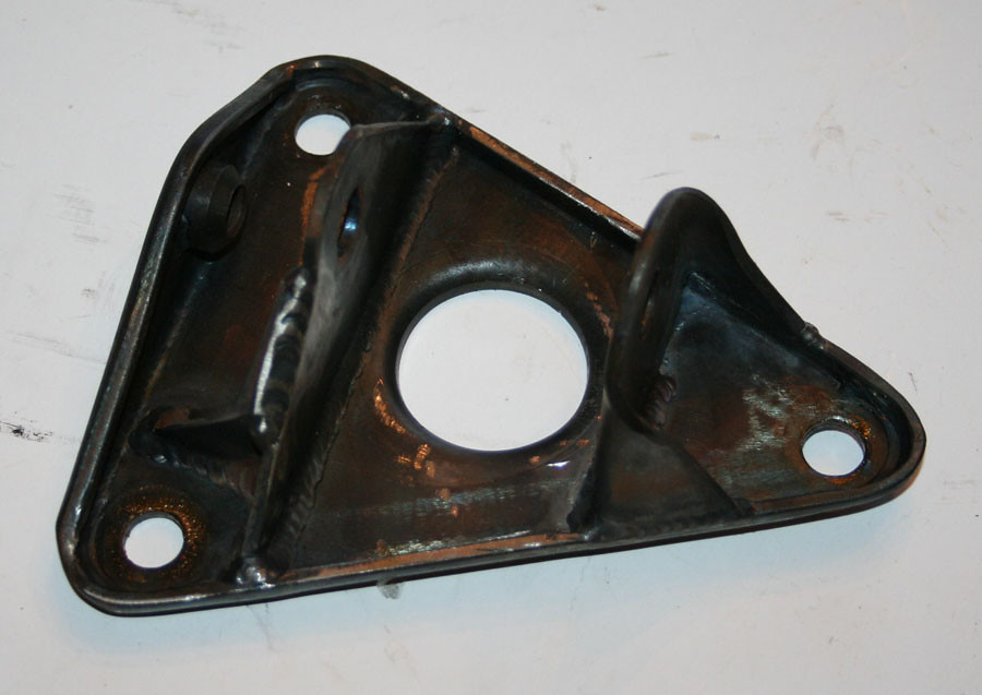
The front engine mounts are done now
Edited by Aubrey_Boy on 7th Jul, 2017. |
||||||
|
690 Posts Member #: 9962 Post Whore |
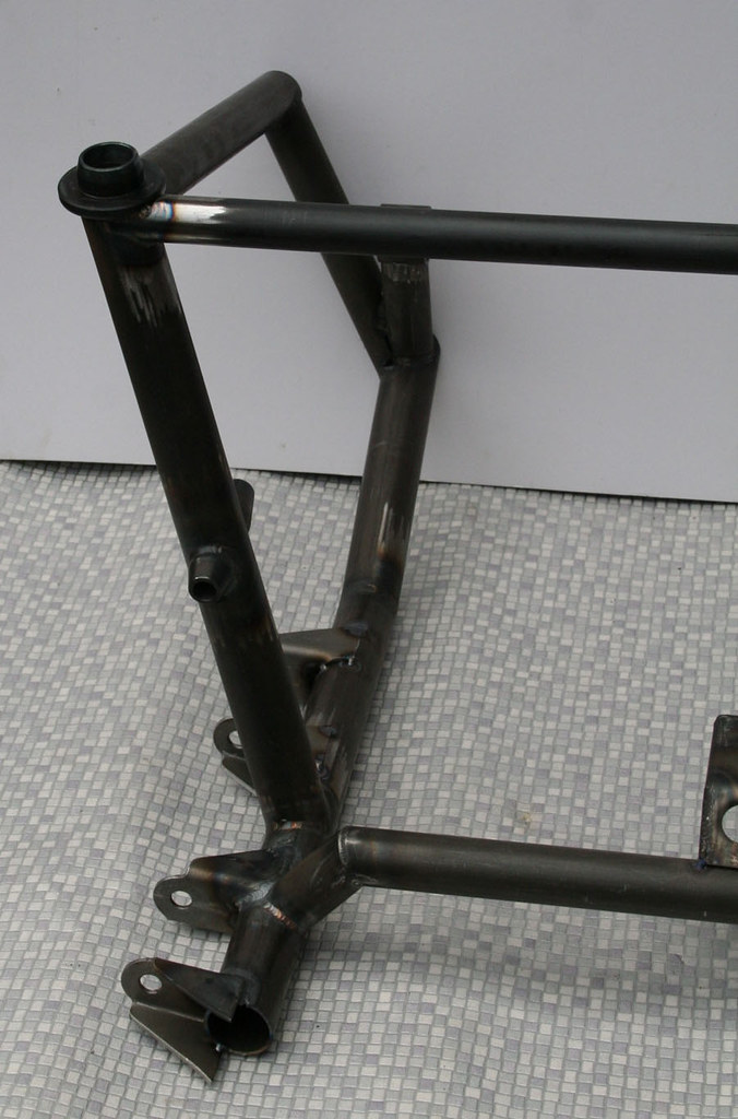
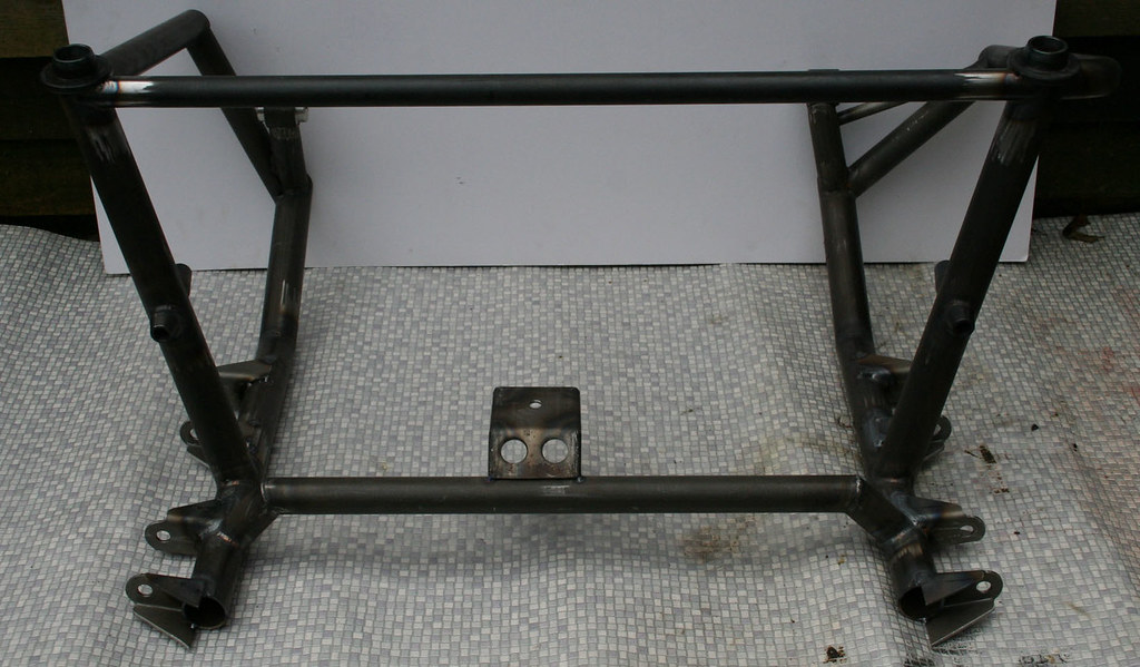
15th Feb, 2013 at 03:51:12pm
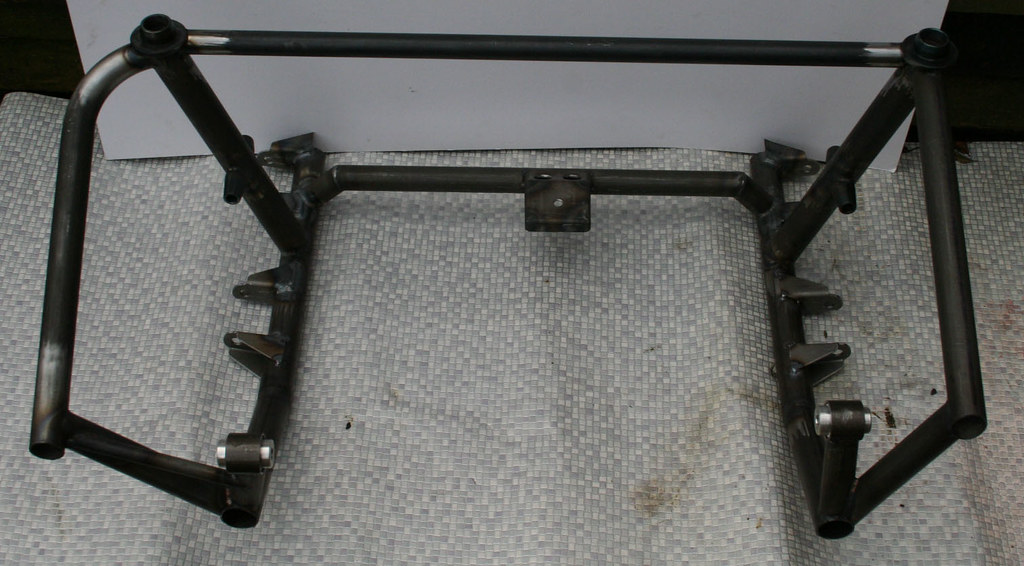
The subframe itself has progressed a bit, still not finished but time to fit to the car and check clearances again
Edited by Aubrey_Boy on 7th Jul, 2017. |
||||||
 299 Posts Member #: 2814 Senior Member Mansfield - Notts |
15th Feb, 2013 at 05:00:39pm
That's looking fantastic, looking foward to more of this build! |
||||||
|
4890 Posts Member #: 1775 Post Whore Chester |
15th Feb, 2013 at 08:03:36pm
Looks very neat... I run a supercharger and I don't care the TB is on the wrong side.
|
||||||
 641 Posts Member #: 9937 Post Whore somewhereintheuniverse near selkirk scotland |
15th Feb, 2013 at 09:54:45pm
very good description and pics mate keep them coming , im fitting a c16se engine in mine using an allspeed frame give em hell |
||||||
|
690 Posts Member #: 9962 Post Whore |
16th Feb, 2013 at 01:30:13pm
Thanks for the kind comments
|
||||||
 2500 Posts Member #: 648 Post Whore Northern Ireland (ex AUS) |
16th Feb, 2013 at 01:45:35pm
Top quality work, you must be a surgeon as a day job. On 7th Nov, 2008 Nic said:
naeJ m !!!!!!sdrawkcab si gnihtyreve ?droabyekym ot deneppah sah tahw ayhwdd |
||||||
|
690 Posts Member #: 9962 Post Whore |
17th Feb, 2013 at 09:55:45pm
Cheers Jay
|
||||||
| Home > Show Us Yours! > Project "Marginal gains..." | |||||||
|
|||||||

| Page: |