
| Page: |
| Home > Technical Chat > Fitting dual wideband 02 sensors | |||||||
|
8604 Posts Member #: 573 Formerly Axel Podland |
13th Oct, 2014 at 09:26:19am
As far as measuring pressure pulses in the turbo manifold are concerned, this is very difficult due to heat. The sensor will need to be very close, if not directly connected to the manifold otherwise the pulses will be lost due to the damping by the connection pipe. As far as I am aware, no such sensor is available. On the 1293 we had to put in quite a length of pipe to get the temperature down enough to stop it melting a rubber hose.
Saul Bellow - "A great deal of intelligence can be invested in ignorance when the need for illusion is deep."
|
||||||
|
8604 Posts Member #: 573 Formerly Axel Podland |
13th Oct, 2014 at 09:32:06am
What would be useful information is the offset caused by heat and pressure on a particular type of installation.
Saul Bellow - "A great deal of intelligence can be invested in ignorance when the need for illusion is deep."
|
||||||
 (2)[/url] by [url=https://www.flickr.com/photos/150672766@N03/]Rod Sugden[/url], on Fli) 5988 Posts Member #: 2024 Formally Retired Rural Suffolk |
13th Oct, 2014 at 10:11:50am
In that scenario, it wouldn't be a fixed offset though as the sample tube one "should" read the actual AFR as it would be unaffected by pressure/temperature variations whereas the directly installed would have a variable offset with varying pressure, and a varying offset with temperatures above 750C (if it proved impossible to limit it to 750C).
Edited by Rod S on 13th Oct, 2014. Schrödinger's cat - so which one am I ??? |
||||||
|
5988 Posts Member #: 2024 Formally Retired Rural Suffolk |
13th Oct, 2014 at 10:24:56am
On 13th Oct, 2014 Paul S said:
As far as measuring pressure pulses in the turbo manifold are concerned, this is very difficult due to heat. The sensor will need to be very close, if not directly connected to the manifold otherwise the pulses will be lost due to the damping by the connection pipe. As far as I am aware, no such sensor is available. On the 1293 we had to put in quite a length of pipe to get the temperature down enough to stop it melting a rubber hose. Good point - when I had considered measuring at the sample chambers it wasn't for pulses but just to see if they were generally equal so the long length of tube wouldn't have worried me. Plus the sample chambers will be a lot cooler by design. Schrödinger's cat - so which one am I ??? |
||||||
|
8604 Posts Member #: 573 Formerly Axel Podland |
13th Oct, 2014 at 10:35:30am
Although I used the singular "offset" in my head I was thinking "offset map" Saul Bellow - "A great deal of intelligence can be invested in ignorance when the need for illusion is deep."
|
||||||
|
696 Posts Member #: 10034 Post Whore Birmingham |
13th Oct, 2014 at 12:20:23pm
The Arduino CAN board I'm looking at is £8 so I might as well trial it. I would use a Proto Shield (veroboard) for basic components , stacked onto the CAN shield, stacked onto the Arduino. I like the idea of the Arduino shields/boards all having the same form factor and header pin-outs, so should stack nice and neatly inside the ECU case and minimal soldering / wiring to do.
|
||||||
|
5988 Posts Member #: 2024 Formally Retired Rural Suffolk |
13th Oct, 2014 at 01:01:59pm
Pictures of the SLC Free here when I played with it
Edited by Rod S on 13th Oct, 2014. Schrödinger's cat - so which one am I ??? |
||||||
|
696 Posts Member #: 10034 Post Whore Birmingham |
13th Oct, 2014 at 01:22:52pm
On 13th Oct, 2014 Paul S said:
As far as measuring pressure pulses in the turbo manifold are concerned, this is very difficult due to heat. The sensor will need to be very close, if not directly connected to the manifold otherwise the pulses will be lost due to the damping by the connection pipe. As far as I am aware, no such sensor is available. On the 1293 we had to put in quite a length of pipe to get the temperature down enough to stop it melting a rubber hose. Also, the sample rate of the o2 sensor will be nowhere near high enough. Whilst this sounds like a very interesting electronics project, I can only see it getting us back to where we were with sample tubes 5 years ago. I don't want to measure the pulse by pulse variations - I want them smoothed out so I get a nice steady reading from cycle to cycle. As you say, the O2 sensor can't react to the pulses, so I want to measure and report them just as the O2 sensor sees them. I assume that the pressure correction that Bosch publishes is also average pressure. Typically, a MAP sensor can see induction pulses very clearly, so I'm expecting pulses to be detectable in the exhaust too. In fact, a long narrow pipe would be ideal. As long as it's sealed at the sensor end, the length will have no effect on mean pressure. I can honestly say that seeing both of you publish your experiments with sample tubes and Megasquirt is the sole reason I joined TurboMinis. This site has shown me that I can do things that others dismiss, and not just copy what's been done before. Please don't see me asking for help on another method as me knocking your solution. In my eyes, your sample chamber solution works perfectly. But this isn't a reason not to resolve a problem. I can learn from this, and if test and conclude it doesn't work, I've still learnt, and have hardware to build sample chambers and other projects. If this solution does work, then we have a second dual wideband solution. If it can be tested and boiled down to the simplest implementation (just 2 sensors directly on the manifold) then that opens the door wider, for others to do it and gather data on their own engines. 5 years is a long time, so you have to ask, why is no one following? EDIT: I'll add that any playing with Arduino is not a solution that I expect anyone to copy, it's just for fact finding and proof. Edited by PhilR on 13th Oct, 2014. |
||||||
|
5988 Posts Member #: 2024 Formally Retired Rural Suffolk |
13th Oct, 2014 at 01:37:27pm
See my edits above re. the 4.9
Edited by Rod S on 13th Oct, 2014. Schrödinger's cat - so which one am I ??? |
||||||
|
5988 Posts Member #: 2024 Formally Retired Rural Suffolk |
13th Oct, 2014 at 02:03:02pm
A better datasheet that confirms the absolute maximums of the 4.9 and where it's accuracy starts to drift - way higher temperature and pressure than the 4.2
Edited by Rod S on 13th Oct, 2014. Schrödinger's cat - so which one am I ??? |
||||||
|
696 Posts Member #: 10034 Post Whore Birmingham |
13th Oct, 2014 at 02:19:27pm
On 13th Oct, 2014 Rod S said:
...if you want to damp them out physically, a long small tube... Otherwise I agree with what you say. Yes, I want to damp them out. A long small tube is what will work the best, but for practical reasons, a small tube that's long enough radiate the heat will suffice, then filter out the pulses with electrics. In my head, I imagine several coils of brake line, with a rubber hose joining it to a pressure sensor. If the data looks good, it would be interesting to see how closely the exhaust pressures related to other sensor data Edited by PhilR on 13th Oct, 2014. |
||||||
|
696 Posts Member #: 10034 Post Whore Birmingham |
13th Oct, 2014 at 02:24:22pm
On 13th Oct, 2014 Rod S said:
A better datasheet that confirms the absolute maximums of the 4.9 and where it's accuracy starts to drift - way higher temperature and pressure than the 4.2 http://industrial.boschautoparts.com/Techn...ambdaSensor.pdf Enjoy. EDIT - obviously designed for lean combustion engines, hence the higher temperature limits, the higher pressure is probably just a side effect. Excellent |
||||||
 6744 Posts Member #: 828 Post Whore uranus |
13th Oct, 2014 at 02:37:38pm
phil,i dont think an mot tester would really react to two bit of brake pipe hidden away somewhere , also you could work out a ratio between the brake pipe area and the inlet hole area ,and just up the inlet hole dia towards parity .
Medusa + injection = too much torque for the dyno ..https://youtu.be/qg5o0_tJxYM |
||||||
|
8604 Posts Member #: 573 Formerly Axel Podland |
13th Oct, 2014 at 02:43:36pm
On 13th Oct, 2014 PhilR said:
In my head, I imagine several coils of brake line, with a rubber hose joining it to a pressure sensor. 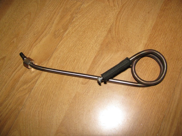
Saul Bellow - "A great deal of intelligence can be invested in ignorance when the need for illusion is deep."
|
||||||
|
696 Posts Member #: 10034 Post Whore Birmingham |
13th Oct, 2014 at 02:47:29pm
Exactly like that. Is that one long enough to stop it melting the hose? |
||||||
|
8604 Posts Member #: 573 Formerly Axel Podland |
13th Oct, 2014 at 03:38:07pm
It never got ran in anger before the project was shelved. Going back in a car soon though Saul Bellow - "A great deal of intelligence can be invested in ignorance when the need for illusion is deep."
|
||||||
|
Forum Mod 10979 Posts Member #: 17 ***16*** SouthPark, Colorado |
13th Oct, 2014 at 03:49:09pm
That looks a little bigger than "brake line"...
On 17th Nov, 2014 Tom Fenton said:
Sorry to say My Herpes are no better Ready to feel Ancient ??? This is 26 years old as of 2022 https://youtu.be/YQQokcoOzeY |
||||||
|
8604 Posts Member #: 573 Formerly Axel Podland |
13th Oct, 2014 at 03:52:22pm
Yes, that's 6mm stainless. I don't believe that brake pipe should go anywhere a hot turbo manifold. Saul Bellow - "A great deal of intelligence can be invested in ignorance when the need for illusion is deep."
|
||||||
|
5988 Posts Member #: 2024 Formally Retired Rural Suffolk |
13th Oct, 2014 at 04:09:49pm
On 13th Oct, 2014 Paul S said:
Yes, that's 6mm stainless. I don't believe that brake pipe should go anywhere a hot turbo manifold. I tend to agree. Although kunifer or copper has much better heat transfer it will just sag under extreme heat. Especially brake line which is relatively small diameter and small wall thickness. IMO better a bit of stainless (properly supported) but longer. Although I'm not worried about the heat transfer on my short sample chamber tubes, I think stainless was the best choice. You could get better mechanical/heat properties with the right grade of alloy "mild" steel but not readily available on eBay and I wouldn't pay market prices for the really good stuff. Schrödinger's cat - so which one am I ??? |
||||||
|
696 Posts Member #: 10034 Post Whore Birmingham |
13th Oct, 2014 at 06:04:31pm
Quick experiment with stainless tubing...
Edited by PhilR on 13th Oct, 2014. |
||||||
|
696 Posts Member #: 10034 Post Whore Birmingham |
13th Oct, 2014 at 06:13:27pm
Duplicate post Edited by PhilR on 13th Oct, 2014. |
||||||
|
5988 Posts Member #: 2024 Formally Retired Rural Suffolk |
13th Oct, 2014 at 06:38:22pm
Is the 70mm a typo (ie, it should say 700mm) or is the thermocouple pushed all the way down the tube to be within 70mm of the flame ?
Edited by Rod S on 13th Oct, 2014. Schrödinger's cat - so which one am I ??? |
||||||
|
6744 Posts Member #: 828 Post Whore uranus |
13th Oct, 2014 at 06:51:38pm
in the past i have measured ex pressure before the 1st turbo ,and between turbo's on a compound twin stage turbo sytem .
Medusa + injection = too much torque for the dyno ..https://youtu.be/qg5o0_tJxYM |
||||||
|
696 Posts Member #: 10034 Post Whore Birmingham |
13th Oct, 2014 at 06:59:47pm
No not a typo - 7cm.
|
||||||
|
696 Posts Member #: 10034 Post Whore Birmingham |
13th Oct, 2014 at 07:15:40pm
Rod, With a sample chamber you're sending the hot gas right through the tube. For a sample chamber, the stainless would work against you as it's a poor conductor of heat it won't radiate the heat effectively, and the exhaust gas gets from one end to the other at almost the same temperature.
Edited by PhilR on 13th Oct, 2014. |
||||||
| Home > Technical Chat > Fitting dual wideband 02 sensors | |||||||
|
|||||||


| Page: |