
| Page: |
| Home > Technical Chat > A Series simulation thread. | |||||||
 2909 Posts Member #: 83 Post Whore Glasgow, Scotland |
23rd Oct, 2014 at 05:25:41pm
valvetrain really has less losses than the crank? even taking into account the valve-train operates at half speed seems counter intuitive! v.interesting. turbo 16v k-series 11.9@118.9 :)
|
||||||
 510 Posts Member #: 1592 Smart Guy! mainland europe near ze germans |
30th Oct, 2014 at 04:52:00pm
The model is based on Patton et al. (1989) and the improved version of Fmep by Sandoval and Heywood (2003)
Edited by Sir Yun on 30th Oct, 2014. That sir, is not rust, it is the progressive mass reduction system
|
||||||
 6744 Posts Member #: 828 Post Whore uranus |
30th Oct, 2014 at 05:26:59pm
doesn't that paper put train loss at 16% and crank at 9% joost ? Medusa + injection = too much torque for the dyno ..https://youtu.be/qg5o0_tJxYM |
||||||
|
510 Posts Member #: 1592 Smart Guy! mainland europe near ze germans |
30th Oct, 2014 at 10:01:09pm
It does , but does not mention for which type of valve train. and is the newer friction model. That said I shall and see if I made a mistake in the Fmep inputs Edited by Sir Yun on 30th Oct, 2014. That sir, is not rust, it is the progressive mass reduction system
|
||||||
|
8604 Posts Member #: 573 Formerly Axel Podland |
31st Oct, 2014 at 04:18:07pm
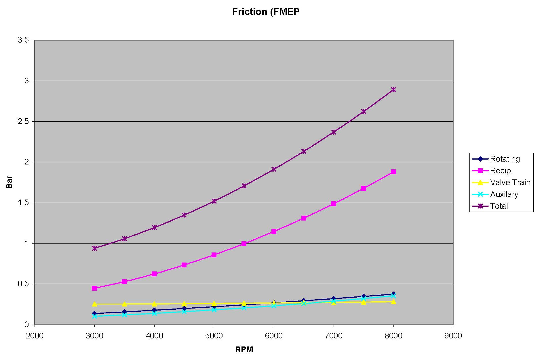
This is the Sandoval & Heywood data for a 998:
Edited by Paul S on 31st Oct, 2014. Saul Bellow - "A great deal of intelligence can be invested in ignorance when the need for illusion is deep."
|
||||||
|
510 Posts Member #: 1592 Smart Guy! mainland europe near ze germans |
31st Oct, 2014 at 11:43:47pm
this is the data as i use it. That sir, is not rust, it is the progressive mass reduction system
|
||||||
|
510 Posts Member #: 1592 Smart Guy! mainland europe near ze germans |
4th Nov, 2014 at 01:44:31pm
This is after working on the burn model (it now uses a turbulent entrainment model to get the values for the Vibe/Wiebe parameters once as otherwise the TE model just takes too long (>7 hours) to do a run . This is about a good as I'm going to get it for now. I did not tweak the model further to force it into shape as that is probably counter productive for the predictive capabilities.
Edited by Sir Yun on 12th May, 2015. That sir, is not rust, it is the progressive mass reduction system
|
||||||
|
6744 Posts Member #: 828 Post Whore uranus |
4th Nov, 2014 at 04:32:51pm
well done joost.
Medusa + injection = too much torque for the dyno ..https://youtu.be/qg5o0_tJxYM |
||||||
|
8604 Posts Member #: 573 Formerly Axel Podland |
4th Nov, 2014 at 06:07:12pm
On 4th Nov, 2014 Sir Yun said:
I tried to model a 6 port head, so two siamese ports in but four proper exhausts out. It looks like the exhaust are quite material to the whole robbing thing, more so than the intakes ports being shared. The exhaust are significant because the outer cylinder exhaust valve is still open when the outer inlet opens and steals the air from the inner cylinder as its inlet valve is just closing. If you get the pulses wrong then it can have a significant impact. That's why an LCB is always first on the list of mods an a NA engine (as an LCB style manifold should also be on a turbo engine, but that's often overlooked in favour of cylinder head mods etc.). I've just read some of your blog. I've never seen higher power output from the inner cylinders as you have. Saul Bellow - "A great deal of intelligence can be invested in ignorance when the need for illusion is deep."
|
||||||
|
510 Posts Member #: 1592 Smart Guy! mainland europe near ze germans |
5th Nov, 2014 at 11:44:59am
it only seems to do that in very specific situations. and I initially made an error in the direction of the flow so the CSA increased the wrong way round . That is all fixed.It still does it a bit though.
That sir, is not rust, it is the progressive mass reduction system
|
||||||
|
8604 Posts Member #: 573 Formerly Axel Podland |
5th Nov, 2014 at 12:14:28pm
I also noticed from your blog that you are treating the junction of the siamese ports within the head as a "plenum".
Saul Bellow - "A great deal of intelligence can be invested in ignorance when the need for illusion is deep."
|
||||||
|
510 Posts Member #: 1592 Smart Guy! mainland europe near ze germans |
5th Nov, 2014 at 08:22:25pm
No/Yes it is treated as a three way joint just like in a collector. however The CSA's and angles are taken from casts I made from a head so it does have the xtra volume as well
That sir, is not rust, it is the progressive mass reduction system
|
||||||
|
8604 Posts Member #: 573 Formerly Axel Podland |
5th Nov, 2014 at 10:12:25pm
Apparently this paper is one of the best references on the subject of junctions:
Saul Bellow - "A great deal of intelligence can be invested in ignorance when the need for illusion is deep."
|
||||||
|
510 Posts Member #: 1592 Smart Guy! mainland europe near ze germans |
10th Nov, 2014 at 09:40:41pm
I tried the size you mentioned for the manifold. so slightly smaller than what I had. Seems to work better.
That sir, is not rust, it is the progressive mass reduction system
|
||||||
|
8604 Posts Member #: 573 Formerly Axel Podland |
12th Nov, 2014 at 09:47:54am
The LCB test is a very good indication that the model is working correctly.
Saul Bellow - "A great deal of intelligence can be invested in ignorance when the need for illusion is deep."
|
||||||
|
510 Posts Member #: 1592 Smart Guy! mainland europe near ze germans |
12th Nov, 2014 at 02:25:14pm
I find it interesting that it mostly affects the inner cylinders. without software you have to to to in cylinder pressure sensors.
That sir, is not rust, it is the progressive mass reduction system
|
||||||
|
8604 Posts Member #: 573 Formerly Axel Podland |
12th Nov, 2014 at 05:04:06pm
The software and pressure sensors serve two different purposes.
Saul Bellow - "A great deal of intelligence can be invested in ignorance when the need for illusion is deep."
|
||||||
 539 Posts Member #: 6807 Post Whore York |
12th Nov, 2014 at 06:42:02pm
On 12th Nov, 2014 Paul S said:
The software and pressure sensors serve two different purposes. The software assists the designer in optimising the performance. The sensors verify the design. You have to build the engine to use the sensors whereas with the software, you can build and test umpteen engines without cutting any metal. From a clean sheet of paper I agree but that is rare and certainly not the case here. Even then though, simulation work is used to get in the ball park of the design spec before the first prototype engine is manufactured and run on the rig. A reverse engineering exercise such as what is going on here, with a current engine configuration requires the model to be correlated against cylinder pressure (and derived burn data) and pressures/temps from the relevant ducts. This allows the Wiebe model and other parameters to be tweaked to bring the model into a correlated state. Simply correlating the power and torque curves by tweaking the model is highly inaccurate and only a small part of the picture. If this was the only goal then a number of engines could all well look very close to an A-series engine on paper Edited by adcyork on 12th Nov, 2014. |
||||||
|
8604 Posts Member #: 573 Formerly Axel Podland |
12th Nov, 2014 at 07:52:56pm
On 12th Nov, 2014 adcyork said:
Simply correlating the power and torque curves by tweaking the model is highly inaccurate and only a small part of the picture. If this was the only goal then a number of engines could all well look very close to an A-series engine on paper I apply simulations to existing infrastructure every day. I earn a lot of money from it and my clients spend £millions based on the results of my simulations and predicted improvements. My judgement is that using these software packages is a very worthwhile exercise to help decide which modifications will work best to improve the engine performance. The final hp or torque values may not be that accurate (neither are the dynos we have available), but the relative gains from specific improvements has consistently been shown to be valid. The 5 port A series is unique due to the siamese ports. Understanding how the siamese ports affects performance is key to the decision making on modifications. I doubt that there are many engines still out there getting this level of attention that look anything like the A Series in simulation terms. Saul Bellow - "A great deal of intelligence can be invested in ignorance when the need for illusion is deep."
|
||||||
|
539 Posts Member #: 6807 Post Whore York |
13th Nov, 2014 at 10:56:19am
On 12th Nov, 2014 Paul S said:
The 5 port A series is unique due to the siamese ports. Understanding how the siamese ports affects performance is key to the decision making on modifications. I doubt that there are many engines still out there getting this level of attention that look anything like the A Series in simulation terms. Precisely, and so correlation of a model from torque and power figures alone is highly inaccurate. Like you say, the dyno's themselves are plagued with inaccuracies through frequent calibration requirement and mechanical variances, so this is why cylinder pressure data from kistler sensors with a high degree of accuracy, accompanied by pressure/temp traces is essential. Without fast response pressure/temp traces from real world data, it is going to be highly iterative to create any form of valid model of these Siamese port structures. For example I see that some discussion has focused around modelling the siamese junction as a plenum with three ducts by Sir Yun. Without any cyl P/duct temp/duct pressure data, how exactly will this modelling philosophy be validated as the best practice? |
||||||
|
8604 Posts Member #: 573 Formerly Axel Podland |
13th Nov, 2014 at 11:35:19am
You have a point if you wish to apply OEM standards. The problem with model calibration is that it is disproportionately expensive to do and in the majority of real world cases, impractical.
Edited by Paul S on 13th Nov, 2014. Saul Bellow - "A great deal of intelligence can be invested in ignorance when the need for illusion is deep."
|
||||||
|
539 Posts Member #: 6807 Post Whore York |
13th Nov, 2014 at 02:36:36pm
I agree model calibration is expensive and time consuming, when OEM standards of accuracy are required.
|
||||||
|
8604 Posts Member #: 573 Formerly Axel Podland |
13th Nov, 2014 at 03:01:11pm
Whilst it would be ideal to have some data to calibrate the models, particularly in respect of the siamese ports, we do have the option of using sensitivity testing to establish if the engine model responds to known improvements as would be expected. This then gives us the confidence that the model is sufficiently reliable to our needs.
Saul Bellow - "A great deal of intelligence can be invested in ignorance when the need for illusion is deep."
|
||||||
|
109 Posts Member #: 10368 Advanced Member Australia |
13th Nov, 2014 at 09:12:57pm
Paul S and Joost, keep the dialogue going. most of it goes well above my head, but the modelling/calibration against known to predict future change trends is seriously good. Paul S , without giving away secrets is the cam in your next build going to be single or scatter? And finally for scatter cams, i gather the more scatter the timing events/valve piston clearance becomes messy, will these models black flag options that cause metal against metal, .. eg scatter of 3 degrees all ok, scatter 5 degrees ERROR reduce lift or timing etc) |
||||||
|
8604 Posts Member #: 573 Formerly Axel Podland |
14th Nov, 2014 at 09:42:45am
On 13th Nov, 2014 Earwax said:
Paul S , without giving away secrets is the cam in your next build going to be single or scatter? And finally for scatter cams, i gather the more scatter the timing events/valve piston clearance becomes messy, will these models black flag options that cause metal against metal, .. eg scatter of 3 degrees all ok, scatter 5 degrees ERROR reduce lift or timing etc) My latest engine has a custom ground scatter cam. However, I sorted it before I started doing the simulations. There are benefits, but they are not significant. The simulation will not pick up metal to metal contact. However, we are talking about very small changes to the LCA. Nothing that will cause a problem unless you are already running close clearances, which is rare on the A Series. Saul Bellow - "A great deal of intelligence can be invested in ignorance when the need for illusion is deep."
|
||||||
| Home > Technical Chat > A Series simulation thread. | |||||||
|
|||||||
| Page: |