
| Page: |
| Home > A-Series EFI / Injection > 1312cc TI | |||||||
 604 Posts Member #: 1106 Post Whore Hungerford, Berks |
20th Oct, 2014 at 07:31:53pm
Just a small offering at this point, but as I found a few minutes I thought Id start a thread on the upcoming Tuning of my Turbo Engine.
77 Clubman build thread
|
||||||
|
8604 Posts Member #: 573 Formerly Axel Podland |
22nd Oct, 2014 at 08:26:20am
Backfire in my opinion.
Saul Bellow - "A great deal of intelligence can be invested in ignorance when the need for illusion is deep."
|
||||||
 9502 Posts Member #: 1023 Post Whore Doncaster, South Yorkshire |
22nd Oct, 2014 at 09:07:46am
Compressor surge?
Edited by Brett on 22nd Oct, 2014. Yes i moved to the darkside |
||||||
|
604 Posts Member #: 1106 Post Whore Hungerford, Berks |
22nd Oct, 2014 at 04:19:07pm
Thanks for the input.
On 22nd Oct, 2014 Paul S said:
How hot was the engine exhaust at this time. You could have had some unburnt fuel in the exhaust. Id guess Very hot. I said a couple of runs in my initial post, this was actually the fourth run. On top of that a lot of stationary running while I messed around with the fuelling at idle and adjusting after the first 3 runs. So not a lot of cooling going on at all. On 22nd Oct, 2014 Brett said:
Edit: do the logs show sync loss and reason ? I had a similar log anomily and exhaust pops at a specific rpm turned out to be a vibration in the alternator belt whipping the crank sensor No lost sync showing on the log. On that note, the logging is still not good. Rod has already pointed out that there is lag in the readings. I was not sure at first how that could be, but now looking through it all in a bit more depth I can see what he means. Possibly down to the version of firmware I am using on the MS2 and the fact that with the IOx and Rods Map carrier board (for the extra MAP, Air temp and MAF) connecting over CAN, Im only seeing runtime data rates of 8 10 /sec. So I may update the MS2 to the latest firmware for tuning, so that the runtime data rates are higher with CAN connected, then drop it back to the version I need for Traction control once I am sorted. 77 Clubman build thread
|
||||||
 (2)[/url] by [url=https://www.flickr.com/photos/150672766@N03/]Rod Sugden[/url], on Fli) 5988 Posts Member #: 2024 Formally Retired Rural Suffolk |
22nd Oct, 2014 at 06:26:33pm
As we've already discussed (off forum, by email) I'm not too worried about the slow data rate. I looks like about 12-14/s on excel.
Schrödinger's cat - so which one am I ??? |
||||||
|
604 Posts Member #: 1106 Post Whore Hungerford, Berks |
23rd Oct, 2014 at 09:31:55am
Around the data rates I was more looking at correlation of Can1 data to MS2 data.
Edited by Graham T on 23rd Oct, 2014. 77 Clubman build thread
|
||||||
|
8604 Posts Member #: 573 Formerly Axel Podland |
23rd Oct, 2014 at 10:38:00am
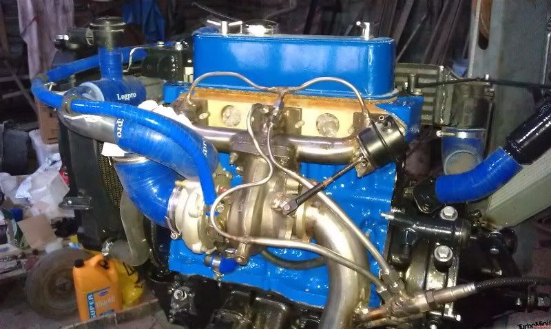
Your sample tubes are too long and too big a diameter from halfway in my opinion.
Saul Bellow - "A great deal of intelligence can be invested in ignorance when the need for illusion is deep."
|
||||||
|
1267 Posts Member #: 831 Post Whore Montreal, Canada |
23rd Oct, 2014 at 03:22:39pm
To speed up the data rate you don't have to remove the CAN device from the project but you can simply click the box in the project properties to disable the runtime data.
Edited by jbelanger on 23rd Oct, 2014. |
||||||
|
604 Posts Member #: 1106 Post Whore Hungerford, Berks |
23rd Oct, 2014 at 06:15:20pm
On 23rd Oct, 2014 Paul S said:
Your sample tubes are too long and too big a diameter from halfway in my opinion. Ok, thanks, taken on board. The larger diameter pipe was supposed to be a way of reducing the Pressure and I imagine as a direct result, the gas velocity that the sensors see. I forget the diameters now, but I THINK 4mm ID going to 8mm ID. I cannot find the receipts on any references to them though. With length, I tried to keep the tubes for both outers and inners the same, hence the inner sample pipe having a few curves in it. For the positioning of the actual sample chambers, it was difficult to locate them any further up the downpipe without their exit into the downpipe being exposed directly to gas coming out of the turbo. I was worried that it may have in some way have disrupted the gas flow exiting the sample chambers. On 23rd Oct, 2014 Paul S said:
Looks like you have a dodgy MAP sensor too. This is a distinct possibility. I have a spare, so can swap it out if necessary. Ill get some testing done on the Jimstim and see whether it reflects what is being seen in the above logs. It could also explain why I am struggling to get the tick over as good as the first time I fired the engine up. On 23rd Oct, 2014 jbelanger said:
To speed up the data rate you don't have to remove the CAN device from the project but you can simply click the box in the project properties to disable the runtime data. Thanks Jean To confirm: Disabling the runtime for device CAN ID increases MS2 runtime data rate to ~55 60 /sec At the same time, it stops the ability to log data from the IOx. As I do not have the LC-1 daisy chain connected, so I cannot see for myself, will the Overwriting of ADC inputs with AFR data / MS2 EGO settings for using remote ports still continue to function? On 23rd Oct, 2014 jbelanger said:
Also, make sure that your AFR lag factor on the MS2 is set to 100. That will have a huge impact on delay. This is the Lambda Averaging lag factor? Rod and I did discuss this mine as set to what I believe is a default of 50. I did read up on it: The algorithm works like this: every sampling period, the new value of anything is computed as (((100 - lag factor) * previous value) + (lag factor * latest sample)) / 100. So if the lag factor is 100, the new value is always 100% of the sampled value. If the factor is 50, it's 50% of the sample + 50% of the old value. And so on... so when you set the lag to 10, the new value is 10% of the sample plus 90% of the previous value. That's pretty heavy averaging I cant remember where that excerpt came from, but I never got to test it out. However, Ill add this to the list of things to try. 77 Clubman build thread
|
||||||
|
1267 Posts Member #: 831 Post Whore Montreal, Canada |
23rd Oct, 2014 at 07:32:48pm
The inter-device CAN traffic is not affect by disabling the runtime data; that is just so that TS stops polling the IOx. The MS2 will still get the data from the IOx.
Edited by jbelanger on 23rd Oct, 2014. |
||||||
|
604 Posts Member #: 1106 Post Whore Hungerford, Berks |
24th Oct, 2014 at 05:38:22am
Thanks for the clarification Jean.
77 Clubman build thread
|
||||||
|
5988 Posts Member #: 2024 Formally Retired Rural Suffolk |
24th Oct, 2014 at 08:03:50am
Although I'm pretty certain I must have seen the photo above some time ago, I either didn't look too closely or I simply missed the significance of the tube diameters, ie, I agree with Paul, that increase in diameter could well add a physical lag to the readings. If it is double the diameter, that's four times the CSA.
Schrödinger's cat - so which one am I ??? |
||||||
|
1267 Posts Member #: 831 Post Whore Montreal, Canada |
24th Oct, 2014 at 03:29:53pm
On 24th Oct, 2014 Rod S said:
From previous discussions with Jean (if I understood it right) I cannot disable polling if I want to see all my three (soon to be four) readings as only two ADCs can be overwritten (Jean, please correct me if I'm wrong). You can overwrite all 8 ADCs if you want. The issue is that you will only have up to 2 AFR values and the other ones will be raw ADC values in the gpioadcX variables. You will need to add some calibration equations in the ini (or custom.ini) to see them as AFR values. But that is not complicated to do. But there is also the issue of the other ADC values on the IOx that you lose when overwriting. You need to disable the overwritten channels so if you use more than 4 ADC channels that you also want to see on the MS2, there's a conflict. |
||||||
|
8604 Posts Member #: 573 Formerly Axel Podland |
24th Oct, 2014 at 03:54:17pm
Did you know that you can connect the 0-5v output from your wideband directly into the ECU ? Saul Bellow - "A great deal of intelligence can be invested in ignorance when the need for illusion is deep."
|
||||||
|
1267 Posts Member #: 831 Post Whore Montreal, Canada |
24th Oct, 2014 at 04:01:40pm
On 24th Oct, 2014 Paul S said:
Did you know that you can connect the 0-5v output from your wideband directly into the ECU ?  And then you have to deal with noise from many sources, with ground offset and with a different 5V reference. Those are a lot more complex to deal with than whatever you need to set to get digital data over CAN. But that's my very biased opinion :) |
||||||
|
8604 Posts Member #: 573 Formerly Axel Podland |
24th Oct, 2014 at 04:05:38pm
You seem to be introducing more sources of error instead.
Saul Bellow - "A great deal of intelligence can be invested in ignorance when the need for illusion is deep."
|
||||||
|
1267 Posts Member #: 831 Post Whore Montreal, Canada |
24th Oct, 2014 at 04:24:04pm
On 24th Oct, 2014 Paul S said:
You seem to be introducing more sources of error instead. Given that the wideband reading itself will vary depending on the distance of the sensor from the valve, you seem to be trying to deal with potential issues (of which I've never had a problem with thousands of miles of actual road use) rather than the real problems. I don't see how there is any error being introduced. The digital value that the controller is computing internally is read directly and transferred to the MS, again digitally. There is no digital to analog conversion with a signal put on a wire exposed to a very nasty environment followed by an analog to digital conversion. All of those will add noise, offset and translation artifacts. And those are real problems for a lot of people. Not having to deal with those makes dealing with the physical constraint much more straightforward. Also, have you checked that you get the exact same value under all circumstances in your MS that you get from the Innovate software with the controller connected to the PC. If not, you don't know if you have an offset and/or voltage reference issue. And are you using any lag on your MS? If so, that's a very crude filtering that does create its own artifacts. |
||||||
|
8604 Posts Member #: 573 Formerly Axel Podland |
24th Oct, 2014 at 04:50:15pm
On 24th Oct, 2014 jbelanger said:
I don't see how there is any error being introduced. The digital value that the controller is computing internally is read directly and transferred to the MS, again digitally. There is no digital to analog conversion with a signal put on a wire exposed to a very nasty environment followed by an analog to digital conversion. All of those will add noise, offset and translation artifacts. And those are real problems for a lot of people. Not having to deal with those makes dealing with the physical constraint much more straightforward. Also, have you checked that you get the exact same value under all circumstances in your MS that you get from the Innovate software with the controller connected to the PC. If not, you don't know if you have an offset and/or voltage reference issue. And are you using any lag on your MS? If so, that's a very crude filtering that does create its own artifacts. I don't disagree if you want the most accurate reading. The main issue is that a few of us on this forum promote fuel injection and the use of dual widebands. Anyone reading those last few posts ^^^ will get an impression that it's very complicated, you need to learn a different language and will be put off. Two widebands directly connected to the ECU is far better than just a singe one downstream of the turbo, even though it may not be as accurate as using serial data via CAN. Saul Bellow - "A great deal of intelligence can be invested in ignorance when the need for illusion is deep."
|
||||||
|
1267 Posts Member #: 831 Post Whore Montreal, Canada |
24th Oct, 2014 at 05:26:05pm
I see your point. I was answering in the context of the setup discussed in this thread.
|
||||||
|
5988 Posts Member #: 2024 Formally Retired Rural Suffolk |
24th Oct, 2014 at 06:50:19pm
Paul,
Schrödinger's cat - so which one am I ??? |
||||||
|
8604 Posts Member #: 573 Formerly Axel Podland |
24th Oct, 2014 at 08:52:09pm
Where does this perception that the 0-5v signal is inaccurate come from?
Saul Bellow - "A great deal of intelligence can be invested in ignorance when the need for illusion is deep."
|
||||||
|
1267 Posts Member #: 831 Post Whore Montreal, Canada |
24th Oct, 2014 at 09:14:13pm
There has been dozens of post on the msextra forum on this. And not all the issues can be solved by simply wiring things better. This is especially true for some controllers such as the AEM but all the controllers I'm aware of have been reported to have issues on some units.
|
||||||
|
604 Posts Member #: 1106 Post Whore Hungerford, Berks |
25th Oct, 2014 at 07:29:17am
On 24th Oct, 2014 Rod S said:
Although I'm pretty certain I must have seen the photo above some time ago, I either didn't look too closely or I simply missed the significance of the tube diameters, ie, I agree with Paul, that increase in diameter could well add a physical lag to the readings. If it is double the diameter, that's four times the CSA. Ok, thanks. Again, taken on board. I found a receipt for some of the pipe and it was 6mm OD with 1mm wall and 8mmOD with 1mm wall, although the picture does seem to suggest a bigger difference than this on the ODs. Ill measure when I next get near the car. On 24th Oct, 2014 Rod S said:
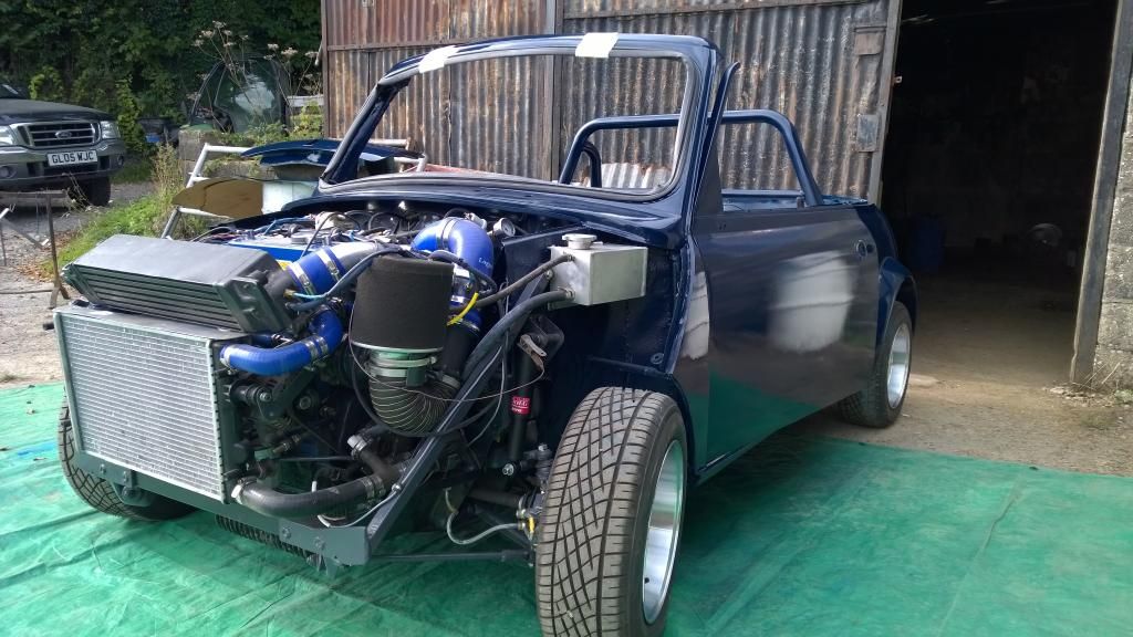
Re. the positioning of the sample chamber exhausts, yours are very little different to mine and have the same angle of entry (which I think also matches Paul's first one) so reversion up the tube is highly unlikely, the main difference is I have short sample tubes and long exits. The biggest problem I came up against was packaging. 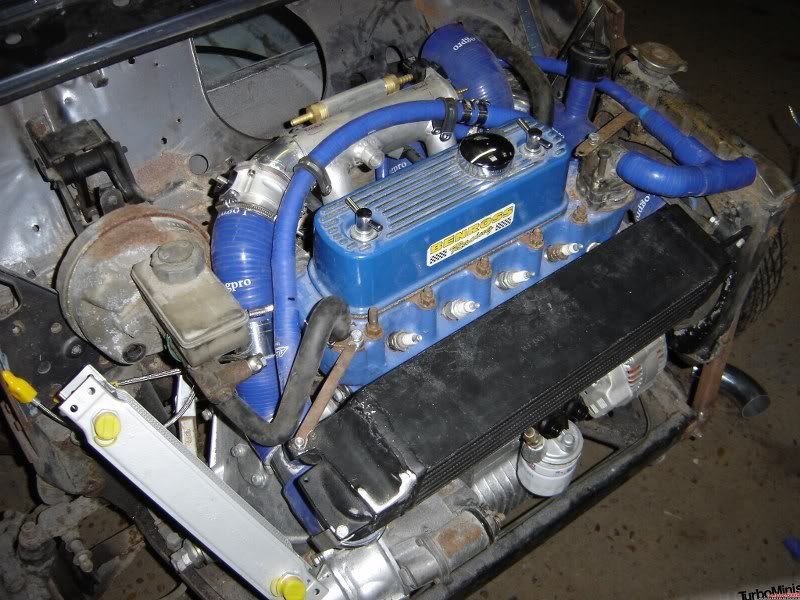
Because I initially thought the car was going to need to go through a BIVA, I wanted to keep most of the brake system as it was in the original car (just to mitigate any nit picking from an examiner). Therefore the Servo was to stay in place, meaning I had to get the Lambda sensors in, but well below the servo, hence the short exit tubes. But since finally finding out from DVLA that I do not need to do the BIVA , but only need to supply pictures of the finished car to get the logbook changed from Saloon to coupe (DVLAs take on the new style, not mine!), I decided that the servo can go. Its next to useless on My Dads Turbo mini and I know a good majority of you all do not use them, so I have no issue with this. However, with the work involved in changing all the sample chamber pipework now, Im going to stay with what I have, at least unless I have to pull the engine out to sort out the oil Pressure problems Even then it may just be a 3rd common wideband in the downpipe to start with. The data presented above is obviously only a very small amount and as it was the first time the engine was run in anger, with all the sensors and electronics coupled up (and the IOx project included with runtime data) theres more work/ testing/tweaking to do before I entertain any significant changes. I just cant handle the thought of pulling this apart again at this moment. Id rather get an MOT and some miles on it so I have more data. 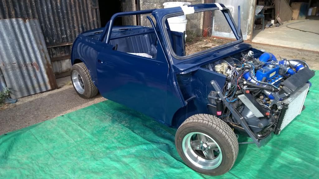 [/URL] [/URL]
 [/URL] [/URL]
 [/URL] [/URL]
Edited by Graham T on 25th Oct, 2014. 77 Clubman build thread
|
||||||
 16540 Posts Member #: 4241 King Gaycharger, butt plug dealer, Sheldon Cooper and a BAC but generally a niceish fella if you dont mind a northerner Rotherham, South Yorkshire |
25th Oct, 2014 at 08:44:23am
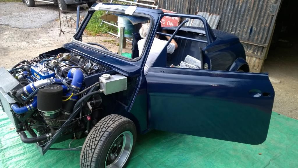
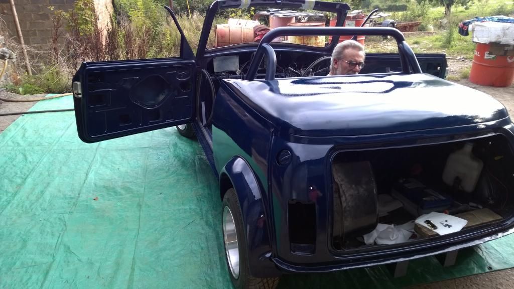
The 'Coupe' conversion turned out nicely. A considerable inprovement over a lot of attempts I've seen in the past. On 11th Feb, 2015 robert said:
i tried putting soap on it , and heating it to brown , then slathered my new lube on it 
|
||||||
|
8604 Posts Member #: 573 Formerly Axel Podland |
25th Oct, 2014 at 09:04:32am
Yep, very nice.
Saul Bellow - "A great deal of intelligence can be invested in ignorance when the need for illusion is deep."
|
||||||
| Home > A-Series EFI / Injection > 1312cc TI | |||||||
|
|||||||


| Page: |