
| Page: |
| Home > A-Series EFI / Injection > New to EFI conversion | |||||||
 (2)[/url] by [url=https://www.flickr.com/photos/150672766@N03/]Rod Sugden[/url], on Fli) 5988 Posts Member #: 2024 Formally Retired Rural Suffolk |
29th Mar, 2016 at 11:33:52am
The procedure for setting the 36-1 wheel up for 90 BTDC varies a bit depending on which manual you read but the aim is - as you say - to achieve the missing tooth passing the sensor 90 degrees before No1 (or No4) reaches TDC.
Schrödinger's cat - so which one am I ??? |
||||||
|
307 Posts Member #: 11231 Senior Member |
29th Mar, 2016 at 11:55:10am
Yes you're right about the cam signal. I misread the sentence in the manual. Thanks for pointing it out mate :) |
||||||
|
8604 Posts Member #: 573 Formerly Axel Podland |
29th Mar, 2016 at 12:50:52pm
On 29th Mar, 2016 Rod S said:
Why you are having to enter 270 degrees, I cannot explain but Paul probably can. I use the MS2 siamese code and the setting that works is 90 degrees for me and the others I know who use the MS2 (unless anyone else knows different). I can't explain why it would be 180 degrees out 
If you have the missing crank tooth at 12 O'clock and the sensor at 9 O'clock, then a setting of 90 degrees should work, assuming that the missing tooth is in the right place (which it probably isn't). This could explain your issues with the ignition outputs. I would get it sorted as this will also affect your injection timing. Saul Bellow - "A great deal of intelligence can be invested in ignorance when the need for illusion is deep."
|
||||||
|
307 Posts Member #: 11231 Senior Member |
29th Mar, 2016 at 12:54:56pm
Yes, the missing tooth is at 12 o'clock and the sensor is at 9 o'clock.
|
||||||
|
8604 Posts Member #: 573 Formerly Axel Podland |
29th Mar, 2016 at 01:12:07pm
On 29th Mar, 2016 Barrieri said:
However I haven't understand what do you mean by "assuming that the missing tooth is in the right place (which it probably isn't)" The missing tooth should be at TDC when the No.1/4 pistons are at TDC. Saul Bellow - "A great deal of intelligence can be invested in ignorance when the need for illusion is deep."
|
||||||
|
307 Posts Member #: 11231 Senior Member |
29th Mar, 2016 at 01:41:32pm
Let me rephrase because I'm getting confused. You are saying "The missing tooth should be at TDC when the No.1/4 pistons are at TDC."
|
||||||
|
8604 Posts Member #: 573 Formerly Axel Podland |
29th Mar, 2016 at 01:54:37pm
Sounds like your hardware is set correctly.
Saul Bellow - "A great deal of intelligence can be invested in ignorance when the need for illusion is deep."
|
||||||
|
307 Posts Member #: 11231 Senior Member |
29th Mar, 2016 at 02:00:22pm
I'm now thinking that since I'm using a coilpack with two coils, I may need to swap the inputs from the ecu to the coil.
|
||||||
|
5988 Posts Member #: 2024 Formally Retired Rural Suffolk |
29th Mar, 2016 at 02:20:11pm
To put it another way, the crank sensor needs to see the missing tooth 90 degrees before TDC on No1 and No4 cylinder.
Schrödinger's cat - so which one am I ??? |
||||||
|
307 Posts Member #: 11231 Senior Member |
29th Mar, 2016 at 02:24:20pm
I'm on it |
||||||
|
307 Posts Member #: 11231 Senior Member |
29th Mar, 2016 at 07:27:35pm
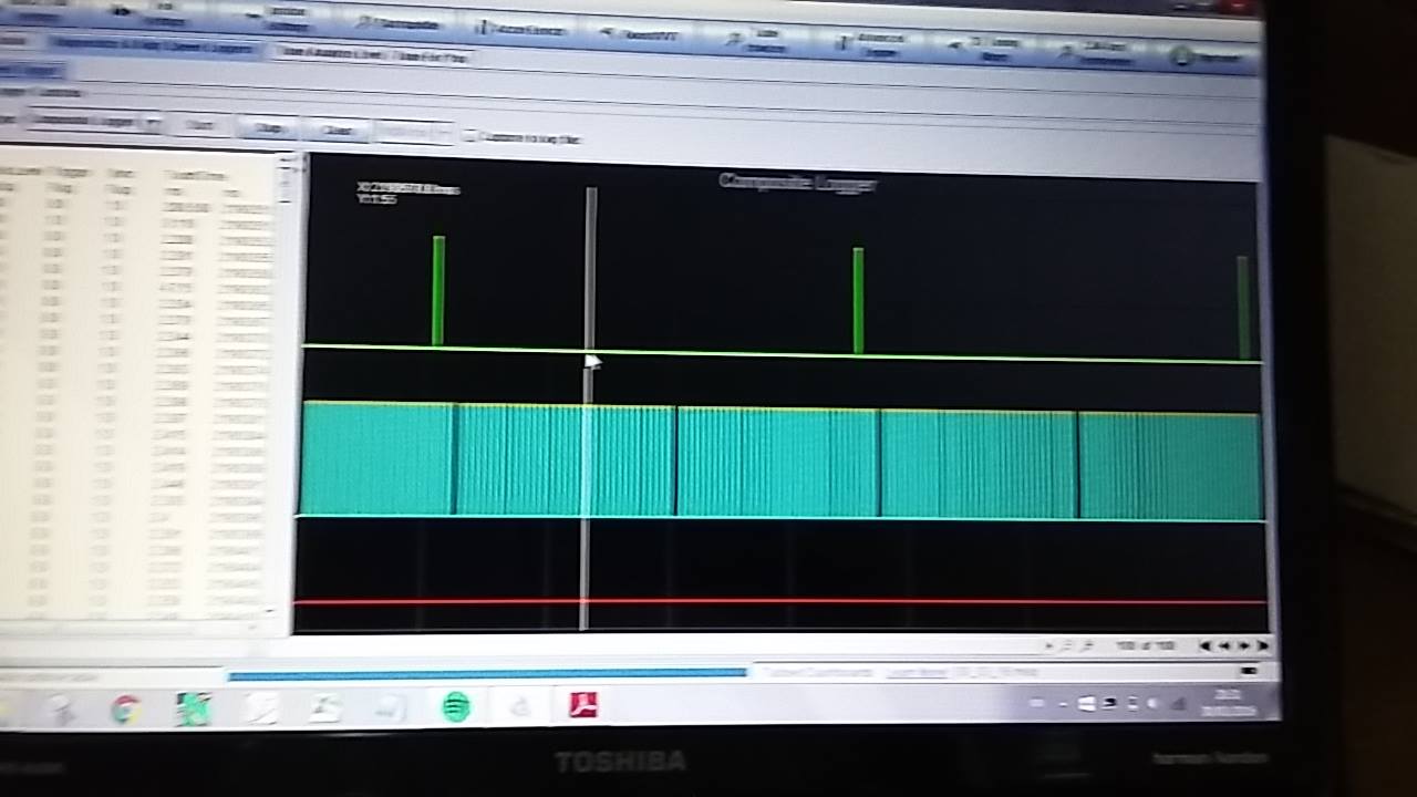
Soo, I checked about the ignition issue. I left the crank wheel as it was but changed the 270deg in the software to 90 as it should be. I also swapped the two logic inputs to the coil pack. Furthermore I changed the orientation of the cam tooth to 120deg BTDC as pointed out by Rod, and in fact the composite logger showed very similar to his. Tomorrow I will post a picture as I forgot to take one when the engine was running.
|
||||||
|
8604 Posts Member #: 573 Formerly Axel Podland |
29th Mar, 2016 at 07:55:32pm
Tip-in is a common problem on engines with relatively large throttles. it can be worse when the engine is cold, so it may not be too bad under real operating conditions.
Edited by Paul S on 29th Mar, 2016. Saul Bellow - "A great deal of intelligence can be invested in ignorance when the need for illusion is deep."
|
||||||
|
307 Posts Member #: 11231 Senior Member |
29th Mar, 2016 at 08:09:50pm
I do agree with you that the inner/outer cylinder problems make it worse. But how do I tackle that ? Just by injection timing and VE table ? I also believe that ignition timing table nakes a huge difference. |
||||||
|
307 Posts Member #: 11231 Senior Member |
30th Mar, 2016 at 08:06:42am
Just a quick thought. Would the tip-in issue be affected if the engine is with/without air cleaner ? Maybe it will delay slightly the flow of air on throttle press. Mine is still without an air cleaner as I need to purchase an MPi one to fit my manifold.
Edited by Barrieri on 30th Mar, 2016. |
||||||
|
307 Posts Member #: 11231 Senior Member |
31st Mar, 2016 at 11:10:54am
Hi guys, yesterday I gave another shot in trying to enriching the outer cylinders. I tried varying the injection timing, together with the VE table and ignition timing. As you said earlier I did notice that by varying slightly the injection timing does make a huge difference in the AFR, however I'm confused in the fact that the wideband on the outer two cylinders is seems to sweep down from rich to lean and back constantly.
Edited by Barrieri on 31st Mar, 2016. |
||||||
|
307 Posts Member #: 11231 Senior Member |
31st Mar, 2016 at 11:14:58am
By the way, attached is the trace of the oscilloscope view I'm getting after having settled the timing issue |
||||||
|
307 Posts Member #: 11231 Senior Member |
31st Mar, 2016 at 11:21:29am
AFR Fluctuations Attachment |
||||||
|
307 Posts Member #: 11231 Senior Member |
31st Mar, 2016 at 11:21:54am
AFR Fluctuations Attachment |
||||||
|
5988 Posts Member #: 2024 Formally Retired Rural Suffolk |
31st Mar, 2016 at 01:30:45pm
Composite tooth log now looks correct but try just doing a screenshot (Alt + PrintScreen on your keyboard) then bung it in "Paint" and save as a jpeg.
Schrödinger's cat - so which one am I ??? |
||||||
|
307 Posts Member #: 11231 Senior Member |
31st Mar, 2016 at 03:00:38pm
Yeah I see what you mean. I currently have just one on the outer cylinders but have bought another for the inner cylinders. I'm waiting for it to arrive.
|
||||||
|
5988 Posts Member #: 2024 Formally Retired Rural Suffolk |
31st Mar, 2016 at 04:16:40pm
On 31st Mar, 2016 Barrieri said:
Do you have any clue however why the only wideband I have just keeps sweeping on values when I'm just not changing anything ? In the clip I attached earlier the engine is idling. Is it configured right in TS as a wideband ? Is it actually a wideband controller/LSU ? That kind of response is from a narrowband sensor. What make and how did you set it in TS ? Schrödinger's cat - so which one am I ??? |
||||||
|
307 Posts Member #: 11231 Senior Member |
31st Mar, 2016 at 09:18:25pm
Mine is an Innovate MTX-L. I think it's an issue of noise. Do you guys know of a good wideband brand ? |
||||||
|
5988 Posts Member #: 2024 Formally Retired Rural Suffolk |
1st Apr, 2016 at 08:58:52am
I've never seen noise swing a gauge around as much as that.
Schrödinger's cat - so which one am I ??? |
||||||
|
307 Posts Member #: 11231 Senior Member |
1st Apr, 2016 at 12:15:06pm
I've connected the yellow wire, as the brown one gives a narrow band response. The physical gauge also does the sweep. The gauge on TS and the actual gauge agree in their readings. Yesterday I tried to ground it directly to the battery instead to the ms3x ground pins. And I think it helped a bit. |
||||||
 6743 Posts Member #: 828 Post Whore uranus |
1st Apr, 2016 at 01:08:03pm
have you got ego control on ?
Medusa + injection = too much torque for the dyno ..https://youtu.be/qg5o0_tJxYM |
||||||
| Home > A-Series EFI / Injection > New to EFI conversion | |||||||
|
|||||||

| Page: |