
| Page: |
| Home > A-Series EFI / Injection > New to EFI conversion | |||||||
|
307 Posts Member #: 11231 Senior Member |
27th Mar, 2016 at 02:04:30pm
Ok then, and when you wire two channels to one injector do you need to place a diode on the channels ? Because I think I would have to do that for the spark eventually.
|
||||||
|
8604 Posts Member #: 573 Formerly Axel Podland |
27th Mar, 2016 at 03:02:39pm
No need for diodes on the injectors. Someone on here has already tested the method of combining the injector outputs.
Saul Bellow - "A great deal of intelligence can be invested in ignorance when the need for illusion is deep."
|
||||||
|
307 Posts Member #: 11231 Senior Member |
27th Mar, 2016 at 03:15:21pm
I was just thinking about that for the spark because with the type of coil pack I'm using, since it only consists of two coils, the same coil must be firing twice consecutively.
|
||||||
|
8604 Posts Member #: 573 Formerly Axel Podland |
27th Mar, 2016 at 05:46:12pm
It is designed to do just that. Saul Bellow - "A great deal of intelligence can be invested in ignorance when the need for illusion is deep."
|
||||||
|
307 Posts Member #: 11231 Senior Member |
27th Mar, 2016 at 09:15:28pm
I think I have figured out why I'm lacking so much power. I noticed that I have a lost sync count of 1.
|
||||||
|
26 Posts Member #: 10785 Member Derby |
28th Mar, 2016 at 07:17:19am
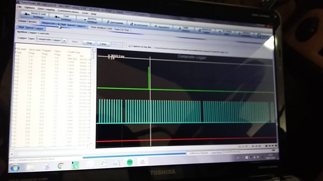
have a look in the tooth logger to confirm there are separate traces for both the crank sensor and cam sensor.
|
||||||
|
8604 Posts Member #: 573 Formerly Axel Podland |
28th Mar, 2016 at 08:43:08am
If the Lost Sync Count is only 1, then there is not a lot wrong.
Saul Bellow - "A great deal of intelligence can be invested in ignorance when the need for illusion is deep."
|
||||||
|
8604 Posts Member #: 573 Formerly Axel Podland |
28th Mar, 2016 at 09:17:23am
On 27th Mar, 2016 Barrieri said:
I think I have figured out why I'm lacking so much power. You're probably not getting any fuel in the outer cylinders. What have you done about the injection timing ?? Saul Bellow - "A great deal of intelligence can be invested in ignorance when the need for illusion is deep."
|
||||||
|
307 Posts Member #: 11231 Senior Member |
28th Mar, 2016 at 04:42:15pm
Good news :)) Today I started out by tweeking a bit the ignition configuration and also changed the spark output from A and C to A and B.
|
||||||
|
307 Posts Member #: 11231 Senior Member |
28th Mar, 2016 at 04:50:18pm
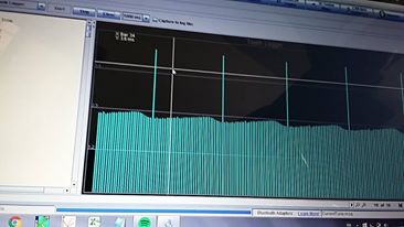
These are the crank and cam signal |
||||||
|
8604 Posts Member #: 573 Formerly Axel Podland |
28th Mar, 2016 at 05:14:10pm
On 28th Mar, 2016 Barrieri said:
When the engine is idling and the AFR is around 13, and I press slightly on the throttle, the outer two cylinders run very lean (about 20) and the engine sounds as if it is working on the inner two pistons. Then if I stay at that same TPS, after a split second the engine runs back at four pistons and the AFR settles to 13 as it should. I tried to resolve this issue by enabling the acceleration enrichment and I guess it helped slightly, but still not to my expectations. The hesitation on applying some throttle is called "Tip-in". It can be tuned out using the VE Map and AE. But you need to get the basic fuel distribution sorted first. Saul Bellow - "A great deal of intelligence can be invested in ignorance when the need for illusion is deep."
|
||||||
|
307 Posts Member #: 11231 Senior Member |
28th Mar, 2016 at 05:17:20pm
Yes I tried playing around slightly with the VE table.
|
||||||
|
8604 Posts Member #: 573 Formerly Axel Podland |
28th Mar, 2016 at 05:22:48pm
On 28th Mar, 2016 Paul S said:
What have you done about the injection timing ?? Saul Bellow - "A great deal of intelligence can be invested in ignorance when the need for illusion is deep."
|
||||||
|
307 Posts Member #: 11231 Senior Member |
28th Mar, 2016 at 05:27:12pm
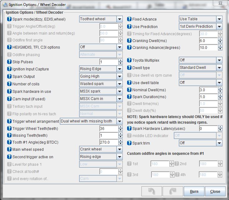
Regarding ignition timing I have used channels A and B and set as per attachment. However I have not yet altered much in the ignition table.
Edited by Barrieri on 28th Mar, 2016. |
||||||
|
307 Posts Member #: 11231 Senior Member |
28th Mar, 2016 at 05:30:20pm
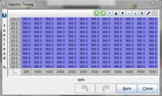
Oh sorry you meant injection timing, I misread it. To be honest I'm not very sure of what it is all about. Currently the table is as per attachment. |
||||||
|
307 Posts Member #: 11231 Senior Member |
28th Mar, 2016 at 05:48:22pm
Do you think I should vary the injection table to account for the tip-in problem ? |
||||||
|
307 Posts Member #: 11231 Senior Member |
28th Mar, 2016 at 05:48:25pm
Do you think I should vary the injection timing table to account for the tip-in problem ? Edited by Barrieri on 28th Mar, 2016. |
||||||
|
8604 Posts Member #: 573 Formerly Axel Podland |
28th Mar, 2016 at 06:10:21pm
On 28th Mar, 2016 Barrieri said:
Do you think I should vary the injection table to account for the tip-in problem ? No, Tip-in is a separate issue. On 28th Mar, 2016 Barrieri said:
To be honest I'm not very sure of what it is all about. To be honest, you need to stop at this point and do some reading and understand the fundemental problems of injecting a siamese port engine. On the A-Series, the holy grail is getting enough fuel into the outer cylinders. This can be done by injecting through the inlet valve when it is open. Hence the injection event needs to ocurr at a specific point of the engine cycle. Have a read of this: http://jbperf.com/sequential/Fuel_Injectin...e_A_Series.html In the meantime, use this table as a guide. This might stop you from damaging the engine: 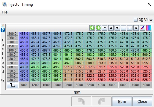
This is for a 998 using Mpi injectors and manifold, so should be in the right ball-park. It's for a boosted application but the 0 to 100 load figures are proven. Saul Bellow - "A great deal of intelligence can be invested in ignorance when the need for illusion is deep."
|
||||||
|
307 Posts Member #: 11231 Senior Member |
28th Mar, 2016 at 06:14:06pm
I have read this quite a long time ago, but as you said its best to do some good reading on the matter to make things clearer. Thanks again mate :) |
||||||
|
307 Posts Member #: 11231 Senior Member |
28th Mar, 2016 at 07:05:20pm
I was reading through your article Paul and noticed this "The cam sensor ensures that the ECU knows when No. 1 cylinder is on its inlet stroke, rather than the power stroke." I've set my cam sensor in line with the cam tooth when cylinder 1 is at compression TDC. I read it from the ms3x hardware manual. Do I need to change it to piston 1 intake TDC instead of compression ? |
||||||
|
8604 Posts Member #: 573 Formerly Axel Podland |
28th Mar, 2016 at 07:42:29pm
On 28th Mar, 2016 Barrieri said:
I was reading through your article Paul and noticed this "The cam sensor ensures that the ECU knows when No. 1 cylinder is on its inlet stroke, rather than the power stroke." I've set my cam sensor in line with the cam tooth when cylinder 1 is at compression TDC. I read it from the ms3x hardware manual. Do I need to change it to piston 1 intake TDC instead of compression ? Saul Bellow - "A great deal of intelligence can be invested in ignorance when the need for illusion is deep."
|
||||||
|
307 Posts Member #: 11231 Senior Member |
28th Mar, 2016 at 07:55:26pm
Ok then |
||||||
|
307 Posts Member #: 11231 Senior Member |
28th Mar, 2016 at 07:56:45pm
It is set such that the cam sensor is in front of the cam tooth when both valves of piston 1 are closed |
||||||
 (2)[/url] by [url=https://www.flickr.com/photos/150672766@N03/]Rod Sugden[/url], on Fli) 5988 Posts Member #: 2024 Formally Retired Rural Suffolk |
29th Mar, 2016 at 07:39:50am
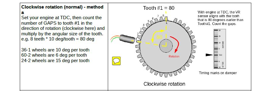
Unless they have changed the manual since I set mine up, it used to say cam trigger should be approx 120 BTDC (assuming a crank wheel missing tooth 90 BTDC).
Schrödinger's cat - so which one am I ??? |
||||||
|
307 Posts Member #: 11231 Senior Member |
29th Mar, 2016 at 10:31:31am
Regarding what you're saying I have a slight misunderstanding I guess... When I was setting my crank trigger wheel which is a 36-1, the procedure used was to put the 1st piston in compression TDC and from the first tooth (engine rotating in clockwise) I placed the crank sensor on the 10th tooth (counting anticlockwise). Which implies that there is 90deg from the first tooth to the crank sensor. However when then I was configuring the megasquirt ignition setup, I had to assign 270deg instead of 90deg.
|
||||||
| Home > A-Series EFI / Injection > New to EFI conversion | |||||||
|
|||||||

| Page: |