
| Page: |
| Home > A-Series EFI / Injection > MSX3 on a 998 Turbo. Cam Sensor, Fuel Injector and Throttle Body Advice. | |||||||
|
21 Posts Member #: 11438 Member Merton, London |
19th Oct, 2016 at 02:05:47pm
Hello.
|
||||||
|
307 Posts Member #: 11231 Senior Member |
19th Oct, 2016 at 02:20:32pm
I'm running a stock MPI manifold, throttle body and injectors on a 998cc with around 7psi boost. I am also using an MS3x. |
||||||
|
8604 Posts Member #: 573 Formerly Axel Podland |
19th Oct, 2016 at 02:44:00pm
Four 630cc/min injectors will be good for up to 150hp. Staged on boost. Saul Bellow - "A great deal of intelligence can be invested in ignorance when the need for illusion is deep."
|
||||||
|
21 Posts Member #: 11438 Member Merton, London |
19th Oct, 2016 at 03:07:30pm
Awesome, one more thing off the list.
|
||||||
|
8604 Posts Member #: 573 Formerly Axel Podland |
19th Oct, 2016 at 03:15:59pm
On 19th Oct, 2016 #Tried It 2 said:
Paul previously you sent me a picture of your converted distributor, and i have a question. I understand that the rotating aluminium top has a square of a specific size which the sensor picks up on. Is the the iron part at the core part of the original distributor? and how did you attach the aluminium cover securely? The previous picture is the latest and is not covered. The rotating top is a piece of steel tube welded to the original dizzy spindle. Cut so that it alternates equally about 180 degrees. This is how I did it on the first attempt: 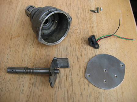
Saul Bellow - "A great deal of intelligence can be invested in ignorance when the need for illusion is deep."
|
||||||
|
8604 Posts Member #: 573 Formerly Axel Podland |
19th Oct, 2016 at 03:19:08pm
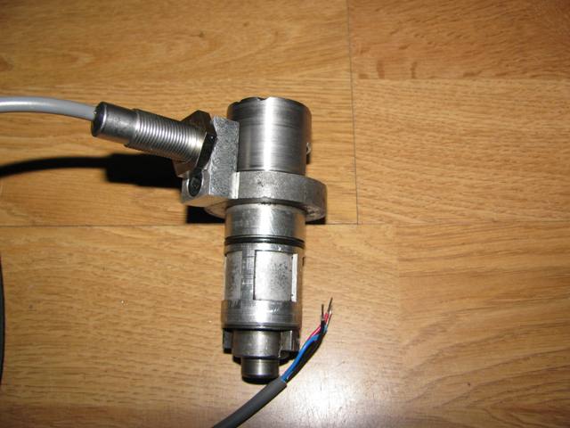
The latest for reference:
Saul Bellow - "A great deal of intelligence can be invested in ignorance when the need for illusion is deep."
|
||||||
|
21 Posts Member #: 11438 Member Merton, London |
19th Oct, 2016 at 07:47:23pm
Sorry, by covered i was referring to the steel tube on your latest design.
|
||||||
|
26 Posts Member #: 10785 Member Derby |
19th Oct, 2016 at 09:10:13pm
some pictures of my cam sensor attempt on my thread. no where near as sophisticated as the other ones on here, but it was cheap and got me on the road :)
|
||||||
|
21 Posts Member #: 11438 Member Merton, London |
19th Oct, 2016 at 09:17:34pm
Hey beejay (haha),
|
||||||
|
8604 Posts Member #: 573 Formerly Axel Podland |
20th Oct, 2016 at 08:43:37am
On 19th Oct, 2016 #Tried It 2 said:
So you hall effect sensor reads the steel and then the perfectly sized cut out gives the the signal that is required. As opposed to reading noting and then the steel tab giving a signal, in your older design? do you have one or two cut outs. The "hole" is 180 degrees cut out of the tube. It's a single cut giving a single on/off per rev. Size and position are not critical as the signal is not used for timing, just phase synching and reference. On 19th Oct, 2016 #Tried It 2 said:
So essentially you strip the dizzy down, retain the spindle and the body. Remove the top of the body from where the clamp retains the standard dizzy. place the spindle back in the dizzy and then weld the piece of steel tube to the spindle, I presume at the top. Then you attach a small oblong of aluminium, with a thread tapped for the sensor. and then use a grub screw to attach the block to the body. Yep. On 19th Oct, 2016 #Tried It 2 said:
I hope you are not offended but i am essentially going to borrow your design, if you don't mind, for my own sensor as i love your compact design. I am going to attempt to us the DIY auto tune hall sensor for my own cam sensor. Do you have any experience with this sensor? The point in sharing is so that people can copy or make their own interpretation. Be careful with the threaded hall sensor selection. The Cherry ones have a higher temperature rating than the Hamlin ones I've used. We've had one fail but not sure why. Saul Bellow - "A great deal of intelligence can be invested in ignorance when the need for illusion is deep."
|
||||||
 (2)[/url] by [url=https://www.flickr.com/photos/150672766@N03/]Rod Sugden[/url], on Fli) 5988 Posts Member #: 2024 Formally Retired Rural Suffolk |
20th Oct, 2016 at 08:45:42am
Here's mine. Not as compact as Paul's latest but very shallow, plenty of room for front mounted rad was my criteria. Uses a slotted opto sensor rather than hall.
Schrödinger's cat - so which one am I ??? |
||||||
|
8604 Posts Member #: 573 Formerly Axel Podland |
20th Oct, 2016 at 09:16:10am
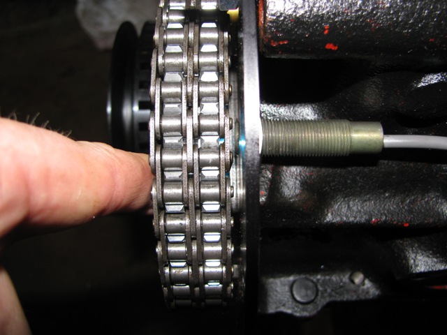
If you are rebuilding the engine you may wish to consider picking up a signal on the cam sprocket:
Saul Bellow - "A great deal of intelligence can be invested in ignorance when the need for illusion is deep."
|
||||||
|
21 Posts Member #: 11438 Member Merton, London |
20th Oct, 2016 at 09:31:18am
So for every complete cycle of four strokes of the engine there are 2 rotation of the cam sensor, this will then give 2 on/off signals per single engine rotation. If you were to make the cut out smaller than 180 would this effect the usability of the signal?
|
||||||
|
5988 Posts Member #: 2024 Formally Retired Rural Suffolk |
20th Oct, 2016 at 09:46:00am
On 20th Oct, 2016 #Tried It 2 said:
So for every complete cycle of four strokes of the engine there are 2 rotation of the cam sensor, this will then give 2 on/off signals per single engine rotation. No, exact opposite. Cam runs at half crank speed. An engine cycle is two crank rotations and one cam hence a single marker (magnetic or optical) gives the cycle location - usually a signal set some time before No.1 cylinder reaching TDC on its firing stroke. Schrödinger's cat - so which one am I ??? |
||||||
|
8604 Posts Member #: 573 Formerly Axel Podland |
20th Oct, 2016 at 09:48:31am
It's one rotation of the cam for 4 strokes.
Saul Bellow - "A great deal of intelligence can be invested in ignorance when the need for illusion is deep."
|
||||||
|
5988 Posts Member #: 2024 Formally Retired Rural Suffolk |
20th Oct, 2016 at 10:00:28am
For a more detailed explanation, consider it like this,
Edited by Rod S on 20th Oct, 2016. Schrödinger's cat - so which one am I ??? |
||||||
|
21 Posts Member #: 11438 Member Merton, London |
23rd Oct, 2016 at 09:58:32pm
I saw the pictures before of the cam sprocket sensor. I really liked the idea, but i have a simplex set up with a stretched IWIS cam chain which i don't want to change and have to the issue of the chain stretching again and no one seems to do a reasonable priced alloy simplex setup. I know Kent did a few years ago but they don't seem to any more, and i think it is MED or swift tune who do one now but its very dear for what it is. If anyone has a Simplex they are willing to sell it would be brilliant if i could have it off you.
|
||||||
|
5988 Posts Member #: 2024 Formally Retired Rural Suffolk |
24th Oct, 2016 at 07:02:49am
On 23rd Oct, 2016 #Tried It 2 said:
.......but does have to be on the inlet stroke of number 1. No, the compression stroke of No1, approx 120 degrees before TDC when cylinder No1 is about to fire. The 120 degrees BTDC (which is the figure for a Megasquirt, other ECUs may use a different value) doesn't have to be dead accurate (mine ended up about 130), the MS simply needs to get the cam signal shortly before the missing tooth on the 36:1 crank wheel passes its sensor which happens at 90 degrees BTDC and to know that it is No1 due to fire rather than No.4, it then sequences everything else (the other three cylinders, the rest of the cycle) by counting from the missing tooth and 35 teeth going past twice. Two revolutions (of the crank) later, it checks again and so on... EDIT - typo Edited by Rod S on 24th Oct, 2016. Schrödinger's cat - so which one am I ??? |
||||||
| Home > A-Series EFI / Injection > MSX3 on a 998 Turbo. Cam Sensor, Fuel Injector and Throttle Body Advice. | |||||||
|
|||||||


| Page: |