
| Page: |
| Home > General Chat > MicroSquirt Engine Woes | |||||||
 (2)[/url] by [url=https://www.flickr.com/photos/150672766@N03/]Rod Sugden[/url], on Fli) 5988 Posts Member #: 2024 Formally Retired Rural Suffolk |
6th Jul, 2017 at 11:23:03pm
On 6th Jul, 2017 Joe C said:
Ah synch loss, does the Microsoft have the vr pots?? Not sure Joe, I thought at least the newer ones have the adaptive chip in them (but I may be getting confused with the newer MS3 stuff). If it has got the VR pots like a normal MS2 their setting is certainly a prime suspect. Which version of microsquirt is it Mike ? One final thought before bed, Mike, email me the whole project file. In TS, menu bar, file, vehicle projects, create project backup. Just save it as some sensible name and email the file. The strange AFR readings may be a wrong setting in the project file (but you also need to tell me which make of wideband it is and how you have it connected). EDIT - bit added. Edited by Rod S on 6th Jul, 2017. Schrödinger's cat - so which one am I ??? |
||||||
|
1267 Posts Member #: 831 Post Whore Montreal, Canada |
7th Jul, 2017 at 12:13:44am
If it's the V3 Microsquirt (plastic cased unit with the connector on top), it has the good tach circuit (MAX9926). Which means there is no adjustment needed.
Edited by jbelanger on 7th Jul, 2017. |
||||||
 6549 Posts Member #: 1149 #1 Basshunter Fan Force Racing ICT Dept Manager Miglia Turbo Am frum Yokshyer tha noes! |
9th Jul, 2017 at 05:31:13pm
Much appreciated chaps, sorry for slow response just got back from Yorkshire War Experience. Heads Burnt to a Crisp.
1/4 Mile 14.3secs 96Mph Terminal 10psi of boost.
|
||||||
|
6549 Posts Member #: 1149 #1 Basshunter Fan Force Racing ICT Dept Manager Miglia Turbo Am frum Yokshyer tha noes! |
11th Jul, 2017 at 11:20:08am
Ok Rod here are the Parameters
On 6th Jul, 2017 Rod S said:
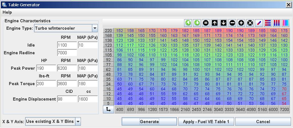
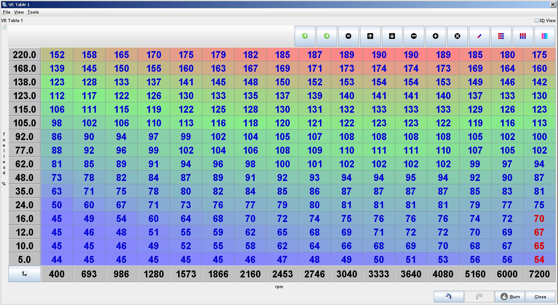
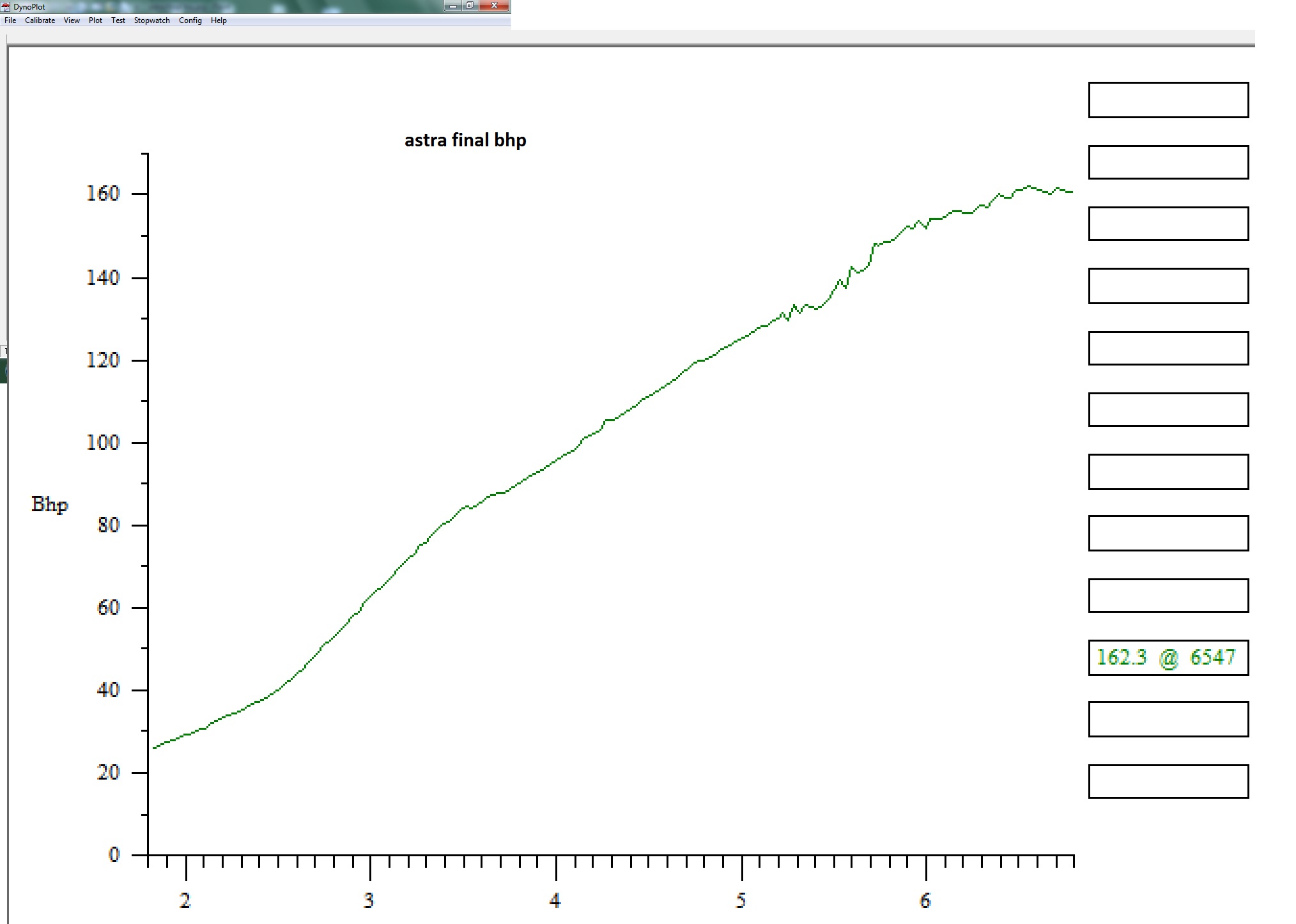
As Joe says, try opening the throttle slowly. To get the fast throttle response right (blipping it or fast acceleration) is a whole load of other settings under the "Accel Enrich" tab in Tunerstudio but ignore that until the VE table is close to being correct. As I said yesterday, and Colin said, your VE table doesn't look right. If the values are too low it won't rev and you will see AFRs go lean even if opening throttle slowly. If you have the registered version of TS (TunerStudio) there is a good table generator that will give you a good starting point. It's not particularly obvious where to find it and if you have the "Lite" (ie, free) version of TS you don't get it along with many other useful tools. If you haven't got the registered version just post up the following parameters and I'll see what the base table looks like and if it's wildly different to yours I'll email it over. Engine size, No. cylinders, Inj flow (in cc/min if you're quoting engine size as cc's, not lbs/hour as some are sold) stoich AFR (which is 14.7 for petrol so I already know that !) Engine type (N/A, turbo, turbo with I/C, supercharged, supercharged with I/C) Expected idle RPM, Expected MAP at idle, RPM redline, Expected peak BHP and at what RPM and what expected MAP (ie, boost) Expected peak torque and at what RPM and MAP. Edited by MikeRace on 11th Jul, 2017. 1/4 Mile 14.3secs 96Mph Terminal 10psi of boost.
|
||||||
|
5988 Posts Member #: 2024 Formally Retired Rural Suffolk |
11th Jul, 2017 at 03:33:36pm
Mike,
On 9th Jul, 2017 MikeRace said: No worries, I was away the weekend too - The Killers headlining BST at Hyde Park on Saturday but I took a sun hat....
Much appreciated chaps, sorry for slow response just got back from Yorkshire War Experience. Heads Burnt to a Crisp. In the project file you have one major issue, in Project Properties you have the "Megasquirt/Microsquirt selection" set as MS2 - this must be changed to "Microsquirt (cased)". Although the workings of the code is essentially the same, and it's the same CPU, for some reason the pin assignment is slightly different which is probably why I can't see a valid AFR reading in the previous datalog. Also, if you have updated, or re-loaded the firmware (as Joe suggested) it is ESSENTIAL you select the microsquirt option, not the MS2 option - it isn't always obvious as it defaults to MS2 - else things will be even worse. I would also suggest you change the temperature setting (in the project) to celcius (if only to make life easier for me...) I've run the VE table generator with the numbers above and, as expected by Colin, Joe (and to some extent myself) I get much higher numbers. A couple of pictures attached, not sure how this will work since I dumped photobucket (I haven't yet got the flikr thing to work for me, I'll try and sort that later.) For the moment I've left them on the same x/y axis values as your previous one to make comparison easier. What I should do is generate it with a better range of MAP values ("load") and a better range of RPM values but can you be sure MAP at idle is really as low as 1.04psi ??? That's only 6.9kPa, I've never seen an engine idle that low even with a tiny cam which I doubt you have. Once we clarify that, I'l re-generate the table and email it to you. HOWEVER...... FIRST YOU MUST FIX THE SYNCH. It's probably as simple as putting a resistor across the VR wires at the microsquirt plug as Jean suggested (i'd forgotten about that issue with 60:2 wheels) but one thing you said in the very first post confuses me. You mention a Bosch adapter ??? With a microsquirt (and most Megasquirt setups) the VR+ and VR- wires should go straight to the unit, nothing inbetween, just in a screened cable with the screen grounded at the microsquirt end. It's particularly important with the later hardware with the adaptive input chip that this is done right. One final point, I'm still seeing a large trigger offset compared to the expected 90 degrees in the base settings. Are you sure that offset was verified by the timing gun or did you not change it in the project settings after testing it ? I'll re-do the table once you confirm the idle MAP (just needs to be approximate, maybe Robert can confirm what his Astra idle MAP is - I may have one of his datalogs somewhere but I haven't filed it anywhere obvious). EDIT - forgot to add, I would also change the basic engine settings to 4 squirts per cycle, alternating (rather than two per cycle simultaneous) but leave that change until last. It doesn't affect the pulse width, just the order, which might better suit the order you have them wired in. In fact there may even be a better combination, I really don't know that much about the non-sequential setups as the siamese code I use is fully sequential (which actually makes life a lot easier, but you need a cam sensor). EDIT 2 - and which make of wideband so I can check the calibration table is correct in the settings ? Edited by Rod S on 11th Jul, 2017. Schrödinger's cat - so which one am I ??? |
||||||
 12307 Posts Member #: 565 Carlos Fandango Burnham-on-Crouch, Essex |
11th Jul, 2017 at 03:49:12pm
good stuff Rod,
On 28th Aug, 2011 Kean said:
At the risk of being sigged... Joe, do you have a photo of your tool? http://www.turbominis.co.uk/forums/index.p...9064&lastpost=1 https://joe1977.imgbb.com/ |
||||||
 6743 Posts Member #: 828 Post Whore uranus |
11th Jul, 2017 at 05:01:09pm
Medusa + injection = too much torque for the dyno ..https://youtu.be/qg5o0_tJxYM |
||||||
|
5988 Posts Member #: 2024 Formally Retired Rural Suffolk |
11th Jul, 2017 at 05:36:13pm
OK,
Schrödinger's cat - so which one am I ??? |
||||||
|
6549 Posts Member #: 1149 #1 Basshunter Fan Force Racing ICT Dept Manager Miglia Turbo Am frum Yokshyer tha noes! |
11th Jul, 2017 at 06:35:02pm
Thats excellent Rod, really appreciate the help! 1/4 Mile 14.3secs 96Mph Terminal 10psi of boost.
|
||||||
|
6743 Posts Member #: 828 Post Whore uranus |
11th Jul, 2017 at 07:26:54pm
i get tickover at 20 inches on the boost guage ,which equates to around 33 on the map Medusa + injection = too much torque for the dyno ..https://youtu.be/qg5o0_tJxYM |
||||||
|
6549 Posts Member #: 1149 #1 Basshunter Fan Force Racing ICT Dept Manager Miglia Turbo Am frum Yokshyer tha noes! |
12th Jul, 2017 at 09:08:29am
Right im slowly ingesting all the Info provided by you kind chaps.
1/4 Mile 14.3secs 96Mph Terminal 10psi of boost.
|
||||||
|
5988 Posts Member #: 2024 Formally Retired Rural Suffolk |
12th Jul, 2017 at 10:09:09am
Sorry for the delay Mike, I got distracted by something else last night.
Edited by Rod S on 12th Jul, 2017. Schrödinger's cat - so which one am I ??? |
||||||
|
6549 Posts Member #: 1149 #1 Basshunter Fan Force Racing ICT Dept Manager Miglia Turbo Am frum Yokshyer tha noes! |
12th Jul, 2017 at 10:24:25am
Cheers Rod,
On 12th Jul, 2017 Rod S said:
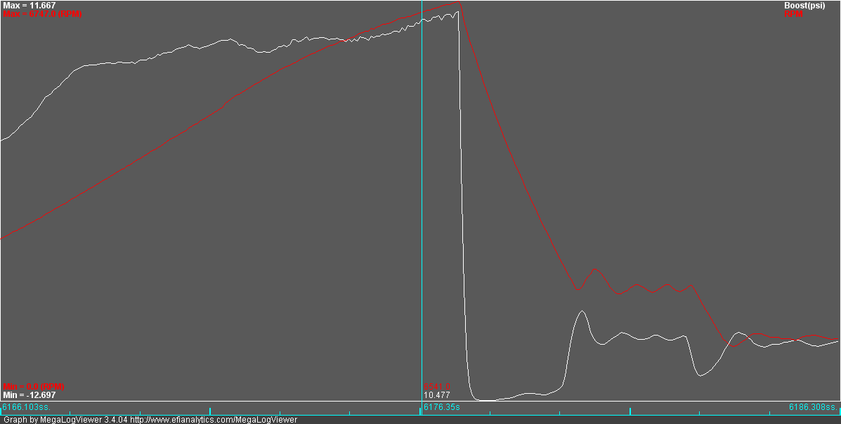
Sorry for the delay Mike, I got distracted by something else last night. For the VE table once I've sorted a revised version I'll email it to you. You can then save your current table and import the one I send, a lot easier than typing it all in. For the resistor, yes, as sketched, so long as there is nothing else involved (I'm still not sure what you meant in the very first post about the Bosch thing). Rather than just watching loss of data, in TunerStudio there is a series of trigger loggers - select "diagnostic and high speed loggers" from the lower menu bar and then select composite logger and "start" and you can see the primary trigger, secondary (if there is one so not in your case) and a loss of sync count all in real time. I think it has limited functionality in the "Lite" version of TS but, IIRC, the limit is something to do with recording, but should still be able to see it. The blue line should show your 60 teeth and a space where the missing two are, the green line will do nothing for you as it's the second trigger, and any spike on the red line is your loss of synch. This data is in the runtime (Megalogviewer) type logs as well (which is why I could see it) but not in an obvious way and not in an easy to understand format. I'll look a bit later at what the PLX wideband outputs, but setting your project to "cased microsquirt" should (I think) at least give some reading rather than the static 12 I saw before. More later. EDIT - typo Edited by MikeRace on 12th Jul, 2017. 1/4 Mile 14.3secs 96Mph Terminal 10psi of boost.
|
||||||
|
5988 Posts Member #: 2024 Formally Retired Rural Suffolk |
12th Jul, 2017 at 10:29:45am
That's fine.
Schrödinger's cat - so which one am I ??? |
||||||
|
6549 Posts Member #: 1149 #1 Basshunter Fan Force Racing ICT Dept Manager Miglia Turbo Am frum Yokshyer tha noes! |
12th Jul, 2017 at 10:36:57am
Will do buddy cheers 1/4 Mile 14.3secs 96Mph Terminal 10psi of boost.
|
||||||
 2909 Posts Member #: 83 Post Whore Glasgow, Scotland |
12th Jul, 2017 at 11:52:26am
On 12th Jul, 2017 MikeRace said:
Cheers Rod, I forgot to mention about the Bosch Bit, I have a Bosch Ignition Driver to Drive my Coil Pack. Like this except the four outputs are simply paired to the two banks of wasted sparks. 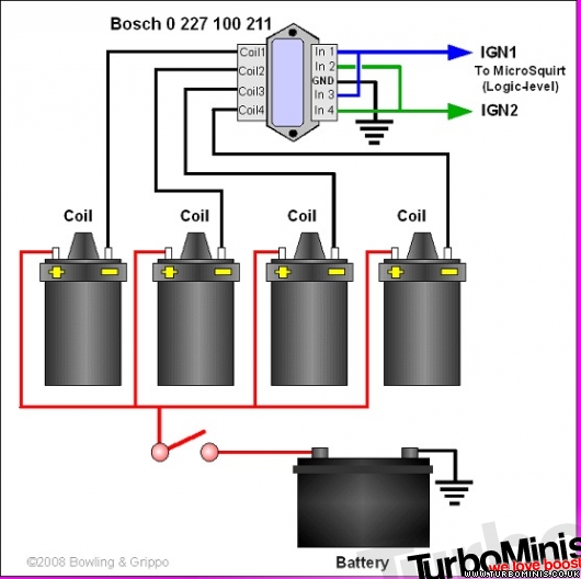
On 12th Jul, 2017 Rod S said: Sorry for the delay Mike, I got distracted by something else last night. For the VE table once I've sorted a revised version I'll email it to you. You can then save your current table and import the one I send, a lot easier than typing it all in. For the resistor, yes, as sketched, so long as there is nothing else involved (I'm still not sure what you meant in the very first post about the Bosch thing). Rather than just watching loss of data, in TunerStudio there is a series of trigger loggers - select "diagnostic and high speed loggers" from the lower menu bar and then select composite logger and "start" and you can see the primary trigger, secondary (if there is one so not in your case) and a loss of sync count all in real time. I think it has limited functionality in the "Lite" version of TS but, IIRC, the limit is something to do with recording, but should still be able to see it. The blue line should show your 60 teeth and a space where the missing two are, the green line will do nothing for you as it's the second trigger, and any spike on the red line is your loss of synch. This data is in the runtime (Megalogviewer) type logs as well (which is why I could see it) but not in an obvious way and not in an easy to understand format. I'll look a bit later at what the PLX wideband outputs, but setting your project to "cased microsquirt" should (I think) at least give some reading rather than the static 12 I saw before. More later. EDIT - typo surely you should just be using in1 and in2 and coil 1 and coil2 and leaving 3&4 disconnected if you only have 2 coils in wasted spark? (the module may not like being ganged up like that) turbo 16v k-series 11.9@118.9 :)
|
||||||
|
5988 Posts Member #: 2024 Formally Retired Rural Suffolk |
12th Jul, 2017 at 11:52:55am
NEXT,
Schrödinger's cat - so which one am I ??? |
||||||
|
6549 Posts Member #: 1149 #1 Basshunter Fan Force Racing ICT Dept Manager Miglia Turbo Am frum Yokshyer tha noes! |
12th Jul, 2017 at 12:35:43pm
Dennis im just going off a Wiring Diagram that said to gang them up but I cant find it. It was on the MS Site somewhere.
1/4 Mile 14.3secs 96Mph Terminal 10psi of boost.
|
||||||
|
6549 Posts Member #: 1149 #1 Basshunter Fan Force Racing ICT Dept Manager Miglia Turbo Am frum Yokshyer tha noes! |
12th Jul, 2017 at 12:41:32pm
Ill pop all these settings up Tonight bud and post up my findings :)
On 12th Jul, 2017 Rod S said:
NEXT, To get the AFRs reading properly, as well as changing the project settings to "cased microsquirt" (which will make sure pin assignment is correct) you must then set TunerStudio running with it connected to your microsquirt, ignition on to power it up but don't start the engine, then go to the very top menu in TS, "tools" then "calibrate AFR table" then select the Inovate/PLX option, then "write to controller". At the moment you have no calibration table loaded so even when you fix the other settings, you need to do this to get a valid AFR reading.. 1/4 Mile 14.3secs 96Mph Terminal 10psi of boost.
|
||||||
|
5988 Posts Member #: 2024 Formally Retired Rural Suffolk |
12th Jul, 2017 at 01:39:08pm
On 12th Jul, 2017 evolotion said:
surely you should just be using in1 and in2 and coil 1 and coil2 and leaving 3&4 disconnected if you only have 2 coils in wasted spark? (the module may not like being ganged up like that) Agreed, The module is to drive four individual primary windings, if you only have two individual primary windings (which a standard Ford coilpack does), just use two of the inputs/outputs or the coilpack might get excessive dwell and overheat. Schrödinger's cat - so which one am I ??? |
||||||
|
6549 Posts Member #: 1149 #1 Basshunter Fan Force Racing ICT Dept Manager Miglia Turbo Am frum Yokshyer tha noes! |
12th Jul, 2017 at 02:38:41pm
Ok chaps,
1/4 Mile 14.3secs 96Mph Terminal 10psi of boost.
|
||||||
|
6549 Posts Member #: 1149 #1 Basshunter Fan Force Racing ICT Dept Manager Miglia Turbo Am frum Yokshyer tha noes! |
12th Jul, 2017 at 02:50:23pm
I cant help think this would be simpler Edited by MikeRace on 12th Jul, 2017. 1/4 Mile 14.3secs 96Mph Terminal 10psi of boost.
|
||||||
|
12307 Posts Member #: 565 Carlos Fandango Burnham-on-Crouch, Essex |
12th Jul, 2017 at 03:07:28pm
NNNOOOOO!!!!!!! On 28th Aug, 2011 Kean said:
At the risk of being sigged... Joe, do you have a photo of your tool? http://www.turbominis.co.uk/forums/index.p...9064&lastpost=1 https://joe1977.imgbb.com/ |
||||||
|
6549 Posts Member #: 1149 #1 Basshunter Fan Force Racing ICT Dept Manager Miglia Turbo Am frum Yokshyer tha noes! |
12th Jul, 2017 at 07:35:18pm
Well chaps it appears ive taken a bit of a step backwards :/
1/4 Mile 14.3secs 96Mph Terminal 10psi of boost.
|
||||||
|
5988 Posts Member #: 2024 Formally Retired Rural Suffolk |
12th Jul, 2017 at 08:16:27pm
Need to see the tooth log, where have you put it ???
Schrödinger's cat - so which one am I ??? |
||||||
| Home > General Chat > MicroSquirt Engine Woes | |||||||
|
|||||||


| Page: |