
| Page: |
| Home > A-Series EFI / Injection > EFI Testing - Dyno Day 6: 1.5:1 Ratio rockers | |||||||
 604 Posts Member #: 1106 Post Whore Hungerford, Berks |
4th Jun, 2019 at 10:35:37pm
Because all the others where 4th gear pulls. That orange trace was 2nd gear, hence boost not as high whilst building up revs.
77 Clubman build thread
|
||||||
|
604 Posts Member #: 1106 Post Whore Hungerford, Berks |
4th Jun, 2019 at 10:35:43pm
Double post Edited by Graham T on 4th Jun, 2019. 77 Clubman build thread
|
||||||
|
604 Posts Member #: 1106 Post Whore Hungerford, Berks |
4th Jun, 2019 at 10:35:46pm
MAP Graph to accompany MAF Graph for Road data
Edited by Graham T on 5th Jun, 2019. 77 Clubman build thread
|
||||||
|
604 Posts Member #: 1106 Post Whore Hungerford, Berks |
4th Jun, 2019 at 10:35:49pm
Road MAF Graph from previous page, re-posted just for easier comparision on the same page:
Edited by Graham T on 5th Jun, 2019. 77 Clubman build thread
|
||||||
|
604 Posts Member #: 1106 Post Whore Hungerford, Berks |
4th Jun, 2019 at 10:35:52pm
This is the MAF Comparison graph of Dyno Runs.
Edited by Graham T on 5th Jun, 2019. 77 Clubman build thread
|
||||||
|
604 Posts Member #: 1106 Post Whore Hungerford, Berks |
5th Jun, 2019 at 07:54:33am
Corresponding MAP data for the above MAF graph
77 Clubman build thread
|
||||||
 6743 Posts Member #: 828 Post Whore uranus |
5th Jun, 2019 at 08:52:23am
how about maf divided by map , to try to get a comparator , or ever sot ...just a line from the date just before cam timing change and a line after ? , just trying to comapre the cam effect . Medusa + injection = too much torque for the dyno ..https://youtu.be/qg5o0_tJxYM |
||||||
|
604 Posts Member #: 1106 Post Whore Hungerford, Berks |
5th Jun, 2019 at 10:16:21am
Here is MAF Over MAP for the 2nd gear road run a few days back and the last but one good Dyno run, -41.
77 Clubman build thread
|
||||||
|
6743 Posts Member #: 828 Post Whore uranus |
5th Jun, 2019 at 10:19:00am
so that looks to have added what 1300 ? rpm Medusa + injection = too much torque for the dyno ..https://youtu.be/qg5o0_tJxYM |
||||||
|
604 Posts Member #: 1106 Post Whore Hungerford, Berks |
5th Jun, 2019 at 12:59:04pm
Im not really sure Robert,
Edited by Graham T on 5th Jun, 2019. 77 Clubman build thread
|
||||||
|
604 Posts Member #: 1106 Post Whore Hungerford, Berks |
4th Jul, 2019 at 03:39:39pm
In the immortal words of the Python boys
Edited by Graham T on 6th Jul, 2019. 77 Clubman build thread
|
||||||
 4619 Posts Member #: 20 My sister is so fit I won't show anyone her picture Lake District |
5th Jul, 2019 at 03:54:16pm
Thats great. I started making something similar to test different runner lengths on my 7port, though nowhere near as fancy as yours, mine simply screwed together to allow different runners to be fitted.
|
||||||
|
4619 Posts Member #: 20 My sister is so fit I won't show anyone her picture Lake District |
5th Jul, 2019 at 03:54:19pm
Double post ! Edited by Turbo Phil on 5th Jul, 2019. |
||||||
|
4619 Posts Member #: 20 My sister is so fit I won't show anyone her picture Lake District |
5th Jul, 2019 at 03:54:21pm
Triple post ! Edited by Turbo Phil on 5th Jul, 2019. |
||||||
|
6743 Posts Member #: 828 Post Whore uranus |
5th Jul, 2019 at 04:43:34pm
this will be very interesting . Medusa + injection = too much torque for the dyno ..https://youtu.be/qg5o0_tJxYM |
||||||
|
8604 Posts Member #: 573 Formerly Axel Podland |
5th Jul, 2019 at 05:05:23pm
Cool.
Saul Bellow - "A great deal of intelligence can be invested in ignorance when the need for illusion is deep."
|
||||||
|
604 Posts Member #: 1106 Post Whore Hungerford, Berks |
6th Jul, 2019 at 09:32:01am
On 5th Jul, 2019 Turbo Phil said:
Thats great. I started making something similar to test different runner lengths on my 7port, though nowhere near as fancy as yours, mine simply screwed together to allow different runners to be fitted. Phil. Phil, that was my original idea, but then I got involved in helping my 9 year niece with robotics at school using Raspberry PIs and Aduinos, which made me think oooh, now theres a plan It is certainly going to be interesting to see how this pans out. My calculations are not as scientific and informed as Paul's, rather more best understanding and urm, just a little guess work. The values I am working off, which may well be based on a completely wrong theory are so different from Paul's above. For example, I know my full runner length, including the distance from the runner flange to the valve stem is around 407mm. (I say around because it is near impossible to accurately measure the curves) I also know that this runner length greatly increased efficiency around the 4000 4500 RPM range. So thats a massive difference to the 400mm at 6037RPM in Pauls above. Apart from the obvious considerations of packaging, I calculated 407mm length based on wanting peek torque around 4500RPM, taking an average inlet temperature in the plenum of 23 Deg C and assuming the best timing for the wave to hit the open valve was at, or just before max lift. To cover the temperature variations I had seen in the plenum, I think it was between 16 Deg C to 35 Deg C, I added 20 Deg advance to my peek lift value, thinking this would ensure the supercharging effect kept at around or just before peek lift. 
On the car that runner length made an immediate difference: I had to increase the values in the 4000RPM and 4500RPM VE fuel table columns by around 4 and 8 points respectively. However, what I did not realise until the first Dyno session with the new runners and plenum was that this had also had the effect of dropping my peek power Revs from between ~5700 5800RPM down to between 5200 5300RPM. We also had to significantly reduce the values in the Fuel VE tables 5500 and 6000RPM columns by up to 16 points. The upshot was that although there was that massive spike in performance around 4000 4500 RPM, I was still stuck at a peek power of around 160 165 BHP without going mad on the boost controller and we know where that ended up. This was the reason I changed the cam timing from 106 to 110 Deg, to try to get the peek power further up the rev range. To date that change looks positive: I have not had to change the VE fuel values around the 4500 RPM range, but I have had to increase values so far by 5 6 points up at 5500 6000 RPM and I believe that is still fairly lean. Once I get brave enough this month, I will get back to the Dyno to check what the differences are. Now back to runner length calcs. My interpretation of the data we got before going boost crazy in Feb suggests that I was wrong with the point at which the shock wave hits the open valve. In fact it seems, possibly the wave hitting the valve just after overlap gives the boost in efficiency. 2 back to back runs from Februarys dyno session 

In both cases above, with the big difference in inlet temperature and the difference in peek torgue RPM, it appears that the calculated point at which the returning wave hits the open valve would have been the same. The other thing I was considering is: If the wave hits so early in the valve opening cycle, then with the second inlet valve 180 deg behind the first on each runner, this means that a second wave would hit the still open valve at the end of the open window?? ( I think, maybe ) So that is all my rambling and bumbling theorising which resulted in me using a target of 210 Deg before the valve closes as the point that I want the wave to hit the open(ing) valve. Thus giving me a range of lengths to fit in: 
So with my existing 407mm long runners, it was again a case of packaging and trying to get somewhere close to my theorised numbers with the largest possible extension range. A graphical representation of the runner movement based on best fit does look a little meandering though... 
Regardless, I guess time will tell Edited by Graham T on 6th Jul, 2019. 77 Clubman build thread
|
||||||
|
6743 Posts Member #: 828 Post Whore uranus |
6th Jul, 2019 at 10:17:48am
graham with the 407 working so well on the dyno at the 4500 area , should there be a 407mm at those rpm in the graph above ? Medusa + injection = too much torque for the dyno ..https://youtu.be/qg5o0_tJxYM |
||||||
|
604 Posts Member #: 1106 Post Whore Hungerford, Berks |
6th Jul, 2019 at 11:00:41am
The problem is that the existing 407mm is mostly curved. In order to get the extending piece in, I need some straight static pipework, so I needed to extend the static pipework at both the bottom of the runner and the top.
77 Clubman build thread
|
||||||
|
6743 Posts Member #: 828 Post Whore uranus |
6th Jul, 2019 at 11:06:41am
ah gotcha thank you
Medusa + injection = too much torque for the dyno ..https://youtu.be/qg5o0_tJxYM |
||||||
|
8604 Posts Member #: 573 Formerly Axel Podland |
6th Jul, 2019 at 07:00:58pm
My memory is a bit hazy on all this stuff, it was some years ago now but I do remember running multiple simulations to optimise the inlet and exhaust runners, cam, turbo, head etc. They all played a big roll in where peak torque occured. Biggest players were the turbine and the exhaust pipe.
Saul Bellow - "A great deal of intelligence can be invested in ignorance when the need for illusion is deep."
|
||||||
|
604 Posts Member #: 1106 Post Whore Hungerford, Berks |
8th Jul, 2019 at 08:04:18am
On 6th Jul, 2019 Paul S said:
Interestingly, the peak of the inlet pressure wave ocurrs at overlap as you discuss above. This was consitently found to be the best solution for the 5 port. Ok, thats good. Thank you, that is now the second confirmation I have had that any efficiency gains that would be expected due to the pulse tuning would happen with the pulse hitting the opening valve on or near to overlap. On 6th Jul, 2019 Paul S said:
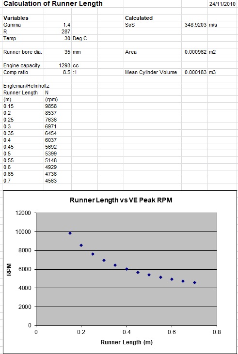
I think this is my latest 998 with a GT1752, LCB style turbo manifold and 300mm manifold runners. Peak torque ocurrs around 6000rpm. Interesting. My little table...
...shows 305mm for 6000RPM on the 8th Harmonic (please correct my terminology if I have it wrong.), that is with a target angle of 210 Deg before valve closing. If I change the temperature from 23Deg to 21 Deg, then that changes runner length to 298mm. Bringing the target angle closer into the overlap area reduces the runner length also for example, setting the target angle to 240 deg, gives me 286mm required runner length. Yesterday I completed the bearing mount for the rear of the lead screw and bolted the assembly together. I seems to work perfectly with a dewalt battery drill powering it, even with a bit of warming all over from a blow torch. I did start the mounting piece for the stepper motor, but that go a bit involved, and so still not completed. I should soon be able to mount the motor and test, then decide whether I need something with more torque, and / or speed. It looks like I need to be able to move the runners the potential 100mm in around 2 seconds as a minimum, but trying to find a log file with a clean first gear tickover to 6000RPM is proving difficult Also, I cannot remember the time it took for 100mm traverse when I had the stepper motor, lead screw and Arduino set up at Christmas. Edited by Graham T on 8th Jul, 2019. 77 Clubman build thread
|
||||||
|
8604 Posts Member #: 573 Formerly Axel Podland |
8th Jul, 2019 at 11:17:16am
On 8th Jul, 2019 Graham T said:
...shows 305mm for 6000RPM on the 8th Harmonic (please correct my terminology if I have it wrong.), that is with a target angle of 210 Deg before valve closing. The software that I use is more akin to CFD. It builds a mesh from the inlet and exhaust geometry, uses characteristics for the compressor and turbine, then does an unsteady simulation of the whole engine air flow every 2 degrees of revolution. It does not use harmonics characteristics although the output reproduces the wave forms. So it does not specifically identify harmonics, they're all in there somewhere :) The other thing to consider is the impact of the exhaust manifold. Another plot I found from years gone by shows how the tuned length of the exhaust is best optimised to deliver lowest pressure at overlap. This is fundemental to a high VE as it promotes effective scavenging. 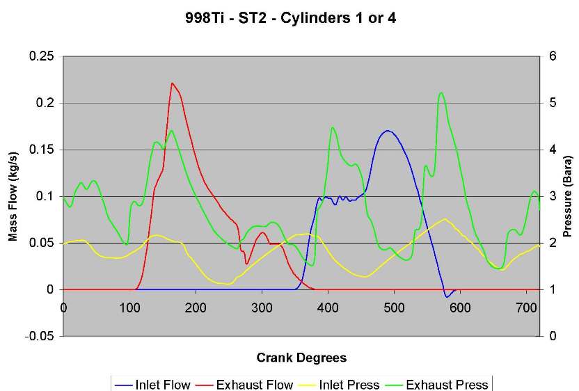
Edited by Paul S on 8th Jul, 2019. Saul Bellow - "A great deal of intelligence can be invested in ignorance when the need for illusion is deep."
|
||||||
 12307 Posts Member #: 565 Carlos Fandango Burnham-on-Crouch, Essex |
8th Jul, 2019 at 12:18:46pm
where you say exhaust pipe, i presume you mean primary length? or do you mean downstream of the turbine.
On 6th Jul, 2019 Paul S said:
My memory is a bit hazy on all this stuff, it was some years ago now but I do remember running multiple simulations to optimise the inlet and exhaust runners, cam, turbo, head etc. They all played a big roll in where peak torque occured. Biggest players were the turbine and the EXHAUST PIPE. You could run loads of simulations on runner length and get no meaningful results because the engine breathing only needs to be restricted by one component and runner length makes no difference. Once everything is truly working together then some big changes in peak torque occurance could be found. I found this chart: 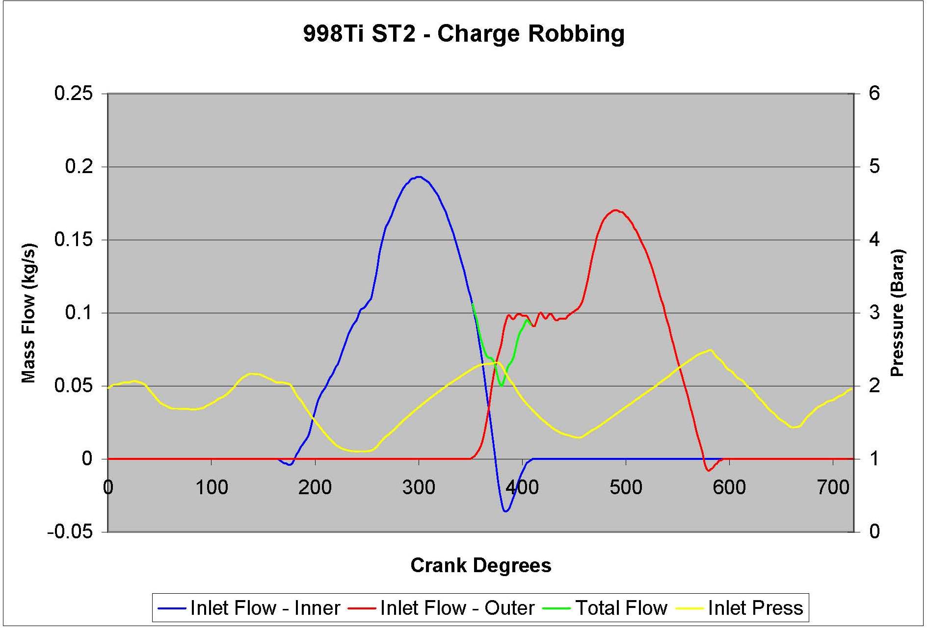
I think this is my latest 998 with a GT1752, LCB style turbo manifold and 300mm manifold runners. Peak torque ocurrs around 6000rpm. Interestingly, the peak of the inlet pressure wave ocurrs at overlap as you discuss above. This was consitently found to be the best solution for the 5 port. Average VE across all cylinders was 100% or thereabouts, mainly due to the scavenging of the exhaust manifold and the inlet pressure wave. However, the difference in VE on the inner/outers was: 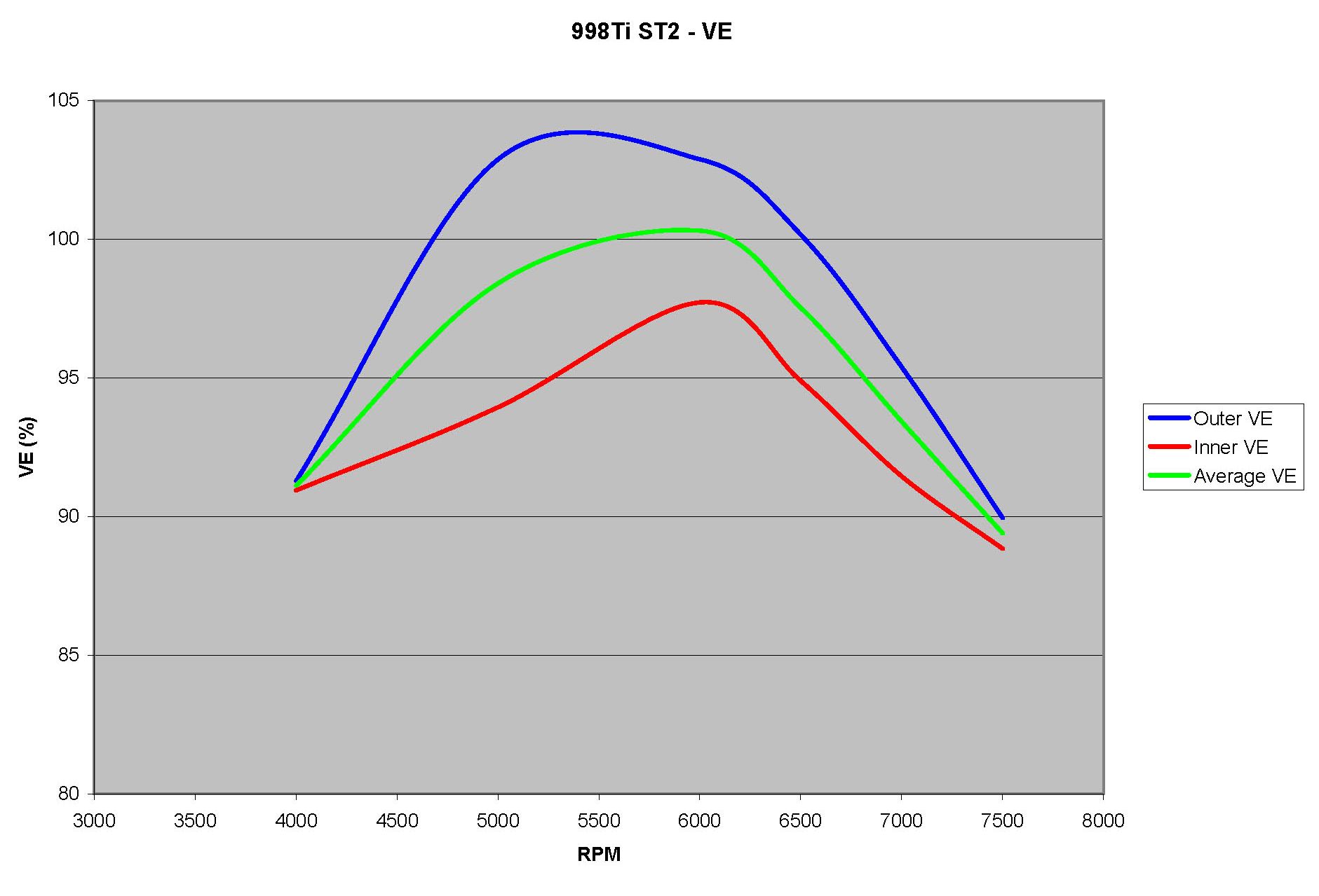
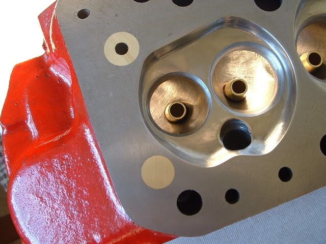
The simulations found that the best solution for the 5 port was to sacrifice the inner cylinders for the sake of the outers. The first chart shows how the outer cylinder fills much faster as it gets a big helping hand from the inner. On 28th Aug, 2011 Kean said:
At the risk of being sigged... Joe, do you have a photo of your tool? http://www.turbominis.co.uk/forums/index.p...9064&lastpost=1 https://joe1977.imgbb.com/ |
||||||
|
8604 Posts Member #: 573 Formerly Axel Podland |
8th Jul, 2019 at 01:03:47pm
On 8th Jul, 2019 Joe C said:
where you say exhaust pipe, i presume you mean primary length? or do you mean downstream of the turbine. No I do mean exhaust pipe, back pressure at overlap is critical and the turbine and the pipe downstream can be very restrictive. Going from 2" to 2 1/4" on the exhaust made a lot of difference in the simulation. Getting primary/secondary lengths right is also critical, but it's more important to get the total length right rather than just the primaries. My 1&4 primaries are about 450mm whereas ideally they would be around 300mm. EDIT: Clarified comment on primaries. Edited by Paul S on 8th Jul, 2019. Saul Bellow - "A great deal of intelligence can be invested in ignorance when the need for illusion is deep."
|
||||||
| Home > A-Series EFI / Injection > EFI Testing - Dyno Day 6: 1.5:1 Ratio rockers | |||||||
|
|||||||


| Page: |