
| Page: |
| Home > A-Series EFI / Injection > EFI Testing - Dyno Day 6: 1.5:1 Ratio rockers | |||||||
 (2)[/url] by [url=https://www.flickr.com/photos/150672766@N03/]Rod Sugden[/url], on Fli) 5988 Posts Member #: 2024 Formally Retired Rural Suffolk |
22nd Jul, 2019 at 05:29:47pm
On 20th Jul, 2019 Joe C said:
While your messing with motors and stuff... Maybe you could add a sprung timing chain /belt tensioner, and a movable one the other side so you can advance/ retard the cam on the fly.... Joe, I don't think there would be enough change in timing just by swapping the chain tension from side to side but there should certainly be enough room inside a duplex cam sprocket to backfit a standard VVT phaser from a small engined VVT setup. Maybe not neatly, but possible. MS2-E has no code for it (MS3 does, but doesn't have the siamese code) but an Arduino could easily cope. But surely the main issue is the single cam. Most VVT deal with inlets and exhausts separately. I presume it can be optimised better by dealing with the two parts of the cycle separately. But it would be an interesting extension to the project. Schrödinger's cat - so which one am I ??? |
||||||
 604 Posts Member #: 1106 Post Whore Hungerford, Berks |
24th Jul, 2019 at 08:12:08am
On 22nd Jul, 2019 Rod S said:
On 20th Jul, 2019 Joe C said:
While your messing with motors and stuff... Maybe you could add a sprung timing chain /belt tensioner, and a movable one the other side so you can advance/ retard the cam on the fly.... Joe, I don't think there would be enough change in timing just by swapping the chain tension from side to side but there should certainly be enough room inside a duplex cam sprocket to backfit a standard VVT phaser from a small engined VVT setup. Maybe not neatly, but possible. MS2-E has no code for it (MS3 does, but doesn't have the siamese code) but an Arduino could easily cope. I would probably use the same Ardiuno as will be used for the Variable length runners. I do not have a cam wheel at hand, but if the cam wheel is 150mm dia, then to move 10 degrees would require around 13mm of linear movement? So that would be a large deflection on the timing chain I think. Lot of research into this to see if it is feasible. On 22nd Jul, 2019 Rod S said:
But surely the main issue is the single cam. Most VVT deal with inlets and exhausts separately. I presume it can be optimised better by dealing with the two parts of the cycle separately. But it would be an interesting extension to the project. Presumable this would not be as efficient solution as with a twin cam setup, but assuming the results I have so far are good, which I see no reason why not, then even with the single cam, being able to swing the cam timing would give some reasonable benefit?? Moving back to data from the Jul Dyno Session: This is the comparison graph between run 41 from Feb and then run -49 from this Jul, so comparing runs which had the same ignition timing. Boost build in Feb was a little lower in the rev range. 
Next, Robert sent me the SOT data earlier in the week, but Ive only just found time to go through it. 
This, just for fun, includes Febs run 44 where the head gasket gave up. Peak there was at 18PSI 
And just to show the difference with BHP and Torque, to get an idea of how the SOT equates: (To make it less messy, I have only used Jim and Roberts data.) This was the last run in Jul 

And then just to finish off: 

77 Clubman build thread
|
||||||
 12307 Posts Member #: 565 Carlos Fandango Burnham-on-Crouch, Essex |
24th Jul, 2019 at 10:02:42am
13 mm deflection and 10 deg Change sounds fine to me, a longer chain would very needed, or you could look at doing it with a belt. (Andy no!! Lol!)
On 28th Aug, 2011 Kean said:
At the risk of being sigged... Joe, do you have a photo of your tool? http://www.turbominis.co.uk/forums/index.p...9064&lastpost=1 https://joe1977.imgbb.com/ |
||||||
 7261 Posts Member #: 1268 The Boom Boom speaker Police! Essex |
24th Jul, 2019 at 10:13:46pm
On 24th Jul, 2019 Joe C said:
13 mm deflection and 10 deg Change sounds fine to me, a longer chain would very needed, or you could look at doing it with a belt. (Andy no!! Lol!) I did look at these oil presure controlled pulleys with a view to adapting them into the K head, but it was all looking a bit far outboard of the cam bearing for my liking, plus it would be easier to just use the fiat head with mappable valve timing.... In the 13's at last!.. Just |
||||||
|
Site Admin  9401 Posts Member #: 58 455bhp per ton 12 sec 1/4 mile road legal mini Sunny Bridgend, South Wales |
25th Jul, 2019 at 08:59:36am
This is amazing progress, keep up the good work Team www.sheepspeed.com Racing
On 15th May, 2009 TurboDave said:
I think the welsh one has it right! 1st to provide running proof of turbo twinkie in a car and first to run a 1/4 in one!! Is your data backed up?? directbackup.net one extra month free for all Turbo minis members, PM me for detials |
||||||
 6743 Posts Member #: 828 Post Whore uranus |
25th Jul, 2019 at 02:42:47pm
Re variable cam timing ,
Medusa + injection = too much torque for the dyno ..https://youtu.be/qg5o0_tJxYM |
||||||
|
12307 Posts Member #: 565 Carlos Fandango Burnham-on-Crouch, Essex |
25th Jul, 2019 at 03:42:18pm
Audi rings a bell for this kind of arrangement. On 28th Aug, 2011 Kean said:
At the risk of being sigged... Joe, do you have a photo of your tool? http://www.turbominis.co.uk/forums/index.p...9064&lastpost=1 https://joe1977.imgbb.com/ |
||||||
|
5988 Posts Member #: 2024 Formally Retired Rural Suffolk |
25th Jul, 2019 at 04:02:28pm
The problem - as I see it - with the A-series is that the chain run is so short.
Schrödinger's cat - so which one am I ??? |
||||||
|
12307 Posts Member #: 565 Carlos Fandango Burnham-on-Crouch, Essex |
25th Jul, 2019 at 04:11:43pm
Hmmmm.... On 28th Aug, 2011 Kean said:
At the risk of being sigged... Joe, do you have a photo of your tool? http://www.turbominis.co.uk/forums/index.p...9064&lastpost=1 https://joe1977.imgbb.com/ |
||||||
|
5988 Posts Member #: 2024 Formally Retired Rural Suffolk |
25th Jul, 2019 at 07:25:34pm
OK Joe, stop teasing....
Schrödinger's cat - so which one am I ??? |
||||||
|
604 Posts Member #: 1106 Post Whore Hungerford, Berks |
26th Jul, 2019 at 07:50:36am
So varying the tension on the timing chain looks like a bit of a no go then
77 Clubman build thread
|
||||||
|
6743 Posts Member #: 828 Post Whore uranus |
26th Jul, 2019 at 09:14:49am
i think this is the sort of thing i was thinking of , its moves the sliders one way or the other .
Medusa + injection = too much torque for the dyno ..https://youtu.be/qg5o0_tJxYM |
||||||
|
12307 Posts Member #: 565 Carlos Fandango Burnham-on-Crouch, Essex |
26th Jul, 2019 at 10:06:32am
LOL Rod
On 28th Aug, 2011 Kean said:
At the risk of being sigged... Joe, do you have a photo of your tool? http://www.turbominis.co.uk/forums/index.p...9064&lastpost=1 https://joe1977.imgbb.com/ |
||||||
|
604 Posts Member #: 1106 Post Whore Hungerford, Berks |
26th Jul, 2019 at 10:47:56am
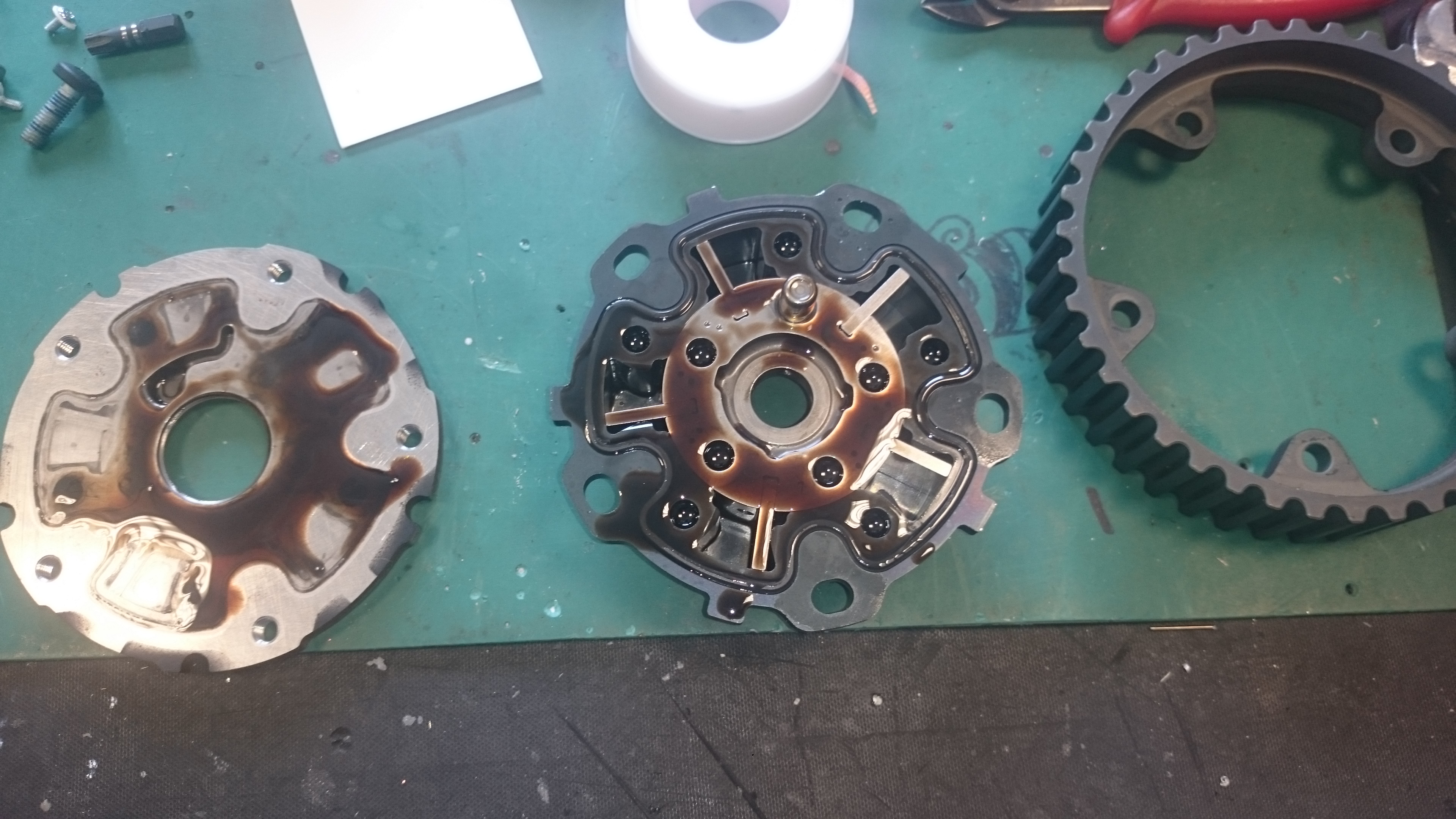
On 26th Jul, 2019 Joe C said:
LOL Rod I think Its from the 5 cyl volvo lump used in the focus RS's... Rod runs outside and starts stripping his engine down to see if his has the same arrangement. 
77 Clubman build thread
|
||||||
|
5988 Posts Member #: 2024 Formally Retired Rural Suffolk |
26th Jul, 2019 at 11:31:15am
On 26th Jul, 2019 Graham T said:
On 26th Jul, 2019 Joe C said:
LOL Rod I think Its from the 5 cyl volvo lump used in the focus RS's... Rod runs outside and starts stripping his engine down to see if his has the same arrangement. LOL - mine's the later 4 cylinder ecoboost version with chain driven VVT cams but there is a lot of technical info on the owners club forum, probably more info on the MK2 (with the Volvo lump) than the Mk3. The technical stuff is all behind a paywall but, as I'm paid up at the moment, I'll have a dig around later. Schrödinger's cat - so which one am I ??? |
||||||
|
12307 Posts Member #: 565 Carlos Fandango Burnham-on-Crouch, Essex |
26th Jul, 2019 at 01:35:23pm
Gratuitous topless shot..... On 28th Aug, 2011 Kean said:
At the risk of being sigged... Joe, do you have a photo of your tool? http://www.turbominis.co.uk/forums/index.p...9064&lastpost=1 https://joe1977.imgbb.com/ |
||||||
|
5988 Posts Member #: 2024 Formally Retired Rural Suffolk |
26th Jul, 2019 at 02:30:54pm
Joe,
Schrödinger's cat - so which one am I ??? |
||||||
|
12307 Posts Member #: 565 Carlos Fandango Burnham-on-Crouch, Essex |
26th Jul, 2019 at 02:46:00pm
105mm, but probably enough meet to trim a little off the outside, maybe down to 100mm.
On 28th Aug, 2011 Kean said:
At the risk of being sigged... Joe, do you have a photo of your tool? http://www.turbominis.co.uk/forums/index.p...9064&lastpost=1 https://joe1977.imgbb.com/ |
||||||
|
5988 Posts Member #: 2024 Formally Retired Rural Suffolk |
26th Jul, 2019 at 04:02:23pm
That could be do-able then.
Schrödinger's cat - so which one am I ??? |
||||||
|
5988 Posts Member #: 2024 Formally Retired Rural Suffolk |
26th Jul, 2019 at 05:46:27pm
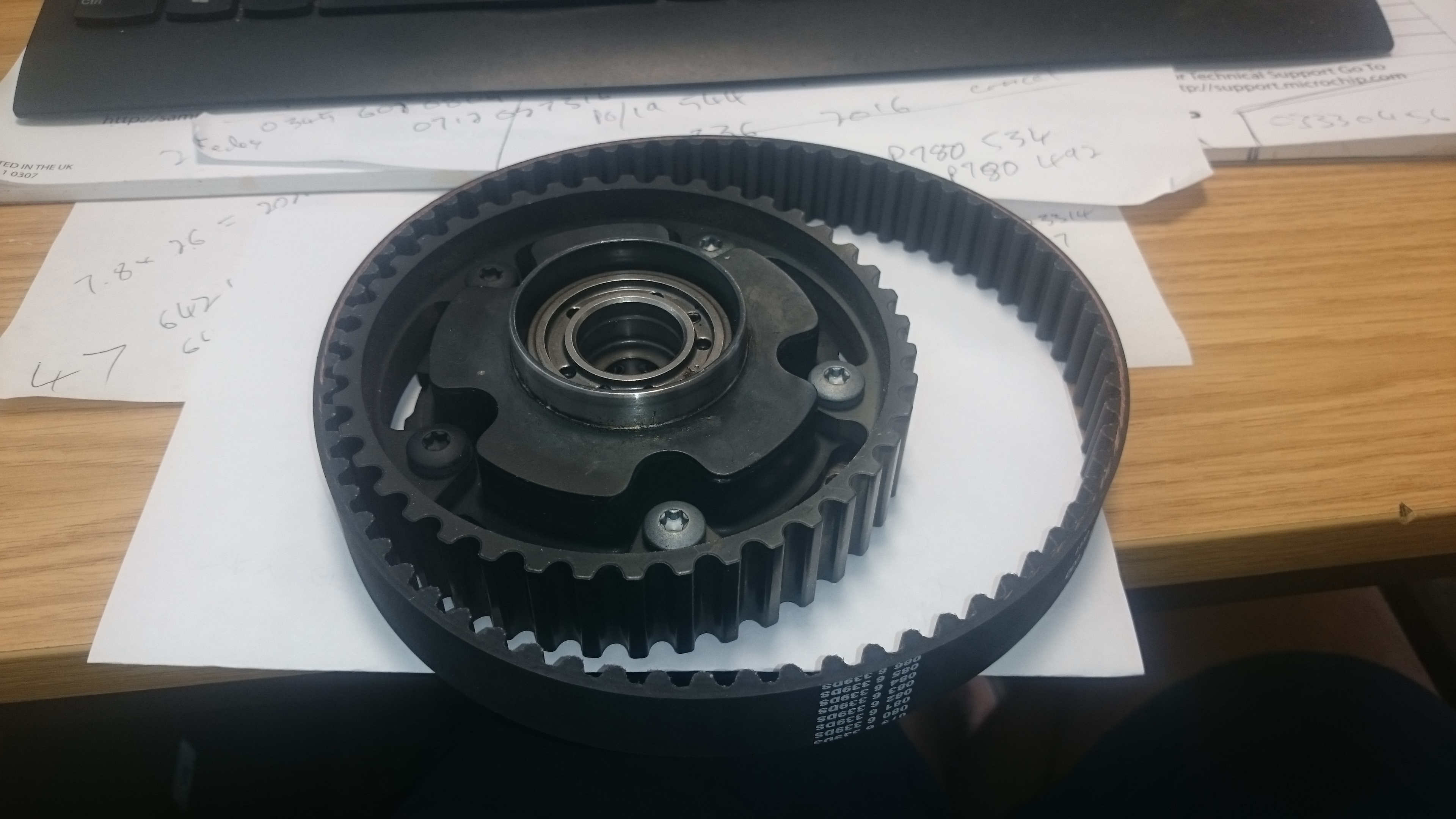
On 26th Jul, 2019 robert said:
i think this is the sort of thing i was thinking of , its moves the sliders one way or the other . https://www.aliexpress.com/item/32852690846.html 
so if mounted in between the chain runs it would take up the slock one way or the other and so change the timing . Interesting thought Robert. I had initially only thought about pushing the chain inwards, like the standard tensioner. But here's the problem in pictures. 
So little space. Now add a chain with two extra links (has to be two minimum and even numbers) and tension it outwards. 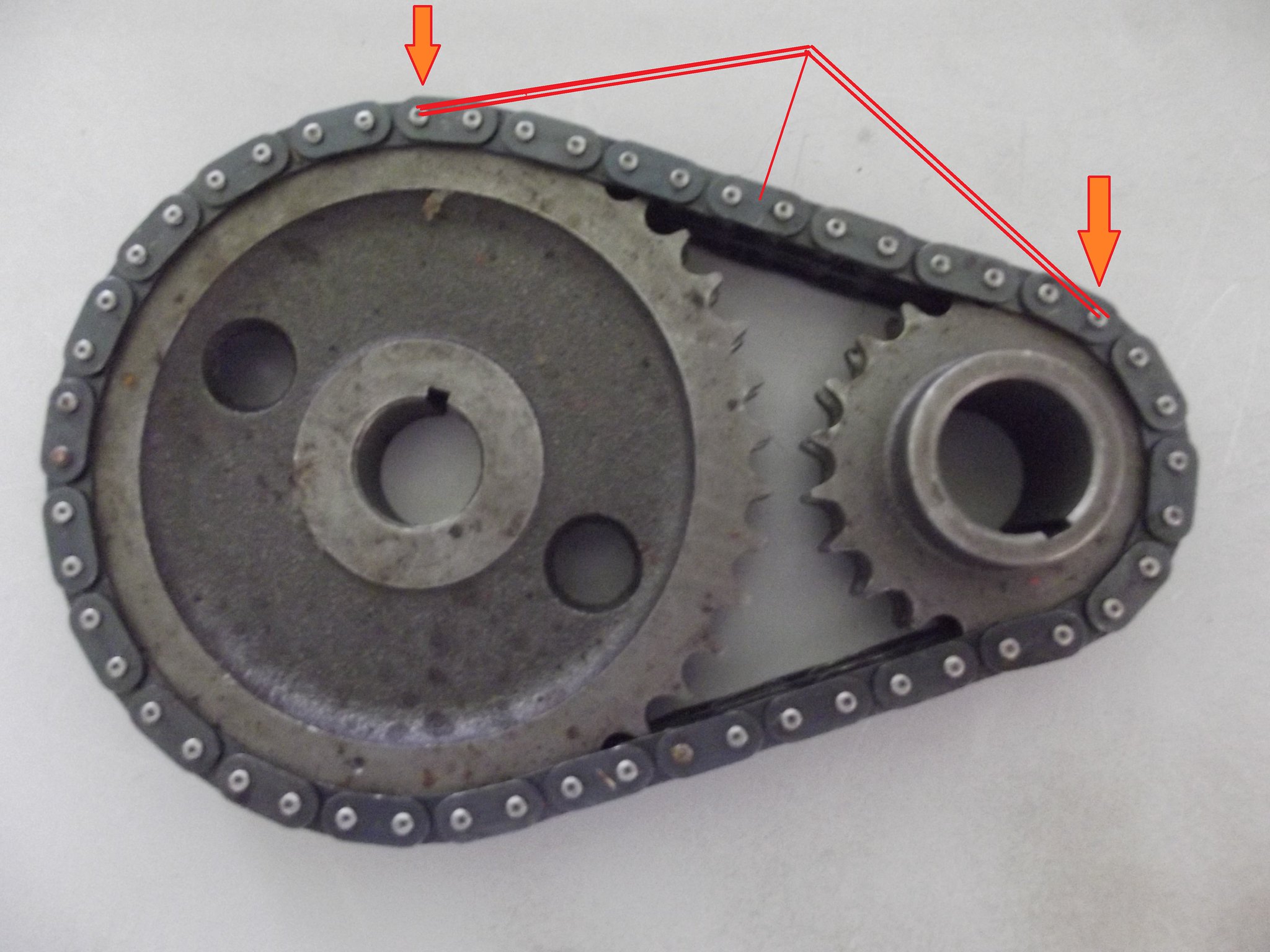 [/url] [/url]
Then look at how small the tensioner pad or roller would have to be,  [/url] [/url]
But we are overlooking the obvious....... The bottom sprocket is only 20 teeth which is a massive 18 degree (crank) per tooth so moving the chain by two tooth's length - which is what we have available with the next longest chain - is 36 crank degrees. So if we only want a 10 degree swing we could start here, 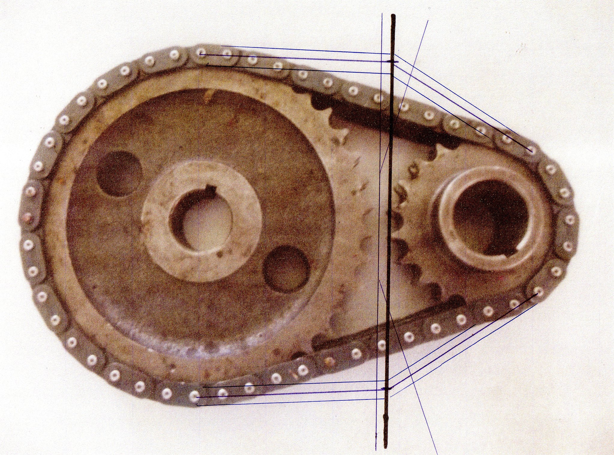 [/url] [/url]
Which would give us +/- 18 But, as we only want +/- 5 the sideways movement should only be about 1/3 Which could give us this,  [/url] [/url]
And could increase the tensioner sizes like this,  [/url] [/url]
But what I haven't considered yet is if we lengthened the chain by four links..... That should give a massive amount of room for the tensioners. I have shown the representation of rollers so far - that in itself is an issue as, at such small diameter, they would have to be profiled to match the chain, not just plain round - but internal blade types may be possible. My only reservation would be how many teeth are left engaged on the bottom sprocket if we start pushing the chain way wider. EDIT - typo Edited by Rod S on 26th Jul, 2019. Schrödinger's cat - so which one am I ??? |
||||||
|
604 Posts Member #: 1106 Post Whore Hungerford, Berks |
27th Jul, 2019 at 07:51:47am
Rod, if you still have this to hand, what are the dimensions as per the below?
77 Clubman build thread
|
||||||
|
5988 Posts Member #: 2024 Formally Retired Rural Suffolk |
27th Jul, 2019 at 10:13:04am
Yes,
Edited by Rod S on 27th Jul, 2019. Schrödinger's cat - so which one am I ??? |
||||||
|
5988 Posts Member #: 2024 Formally Retired Rural Suffolk |
27th Jul, 2019 at 10:32:18am
Forgot to add....
Schrödinger's cat - so which one am I ??? |
||||||
|
5988 Posts Member #: 2024 Formally Retired Rural Suffolk |
27th Jul, 2019 at 12:15:47pm
On 27th Jul, 2019 Graham T said:
Rod, if you still have this to hand, what are the dimensions as per the below? 
The radius' at the points marked are 2.38978" for the big sprocket and 1.19858" for the little sprocket. I have a very accurate 12" plastic ruler...... Not really..... because the chain links are straight the sprockets aren't really round but are a Tetracontagon and an Icosagon with an edge length of 0.375" (the chain pitch) so there are formulas available (Google is your friend). I just double checked with a ruler. The length is a bit more vague because, without knowing the design distance between centres or how much this chain is worn and actually needs tensioning, I actually had to measure it.... Just a touch over 3.75", ie. just over 10 chain links as in the photo. I've yet to find the backplate (it's raining here so I can't move anything out of the garage until it stops) so that and the cover will be later. Schrödinger's cat - so which one am I ??? |
||||||
|
604 Posts Member #: 1106 Post Whore Hungerford, Berks |
28th Jul, 2019 at 08:39:27am
OK Rod,
77 Clubman build thread
|
||||||
| Home > A-Series EFI / Injection > EFI Testing - Dyno Day 6: 1.5:1 Ratio rockers | |||||||
|
|||||||


| Page: |