
| Page: |
| Home > A-Series EFI / Injection > EFI Testing - Dyno Day 6: 1.5:1 Ratio rockers | |||||||
 6743 Posts Member #: 828 Post Whore uranus |
3rd Jan, 2018 at 11:13:56am
the map window thing i was thinking may be affecting the signal .. Medusa + injection = too much torque for the dyno ..https://youtu.be/qg5o0_tJxYM |
||||||
 604 Posts Member #: 1106 Post Whore Hungerford, Berks |
4th Jan, 2018 at 09:27:58am
On 3rd Jan, 2018 Paul S said:
A good comparison would be the VE curve you did ^^^. It will factor MAP out of the equation. Certainly is a problem with boost building and the finger must point to the new turbo. I could be Paul, Im just hoping not. At 2000RPM and below all the Remote Turbo logs indicate it was slower to build boost than the SRE session (with the log manifold). With the RR Day 1 5.6PSI run the boost is slow to build up initially, but then at 2400RPM it ramps up and follows the SRE boost curve until the Wastegate opens. The next logged run on RR Day 1 was the 7.1PSI run, where it builds no boost until ~2600RPM, and then the curve follows both the SRE and RR day 1 curve until the Wastegate opens (at much lower boost), levels off and then builds boosts again up to its peak. The only thing I can see that changed between the two RR day 1 runs in the above graph would have been the injection timing and the boost duty cycle. The 5.6PSI run was base pressure with no Boost controller bleed off, the second run was at 22% Boost duty cycle. ooh, and the sample chamber EGT was massively lower in the second (7.1PSI) run. At 2296RPM for example, for the 5.6PSI run the EGT was at 111DegC where as for the 7.1PSI run it was at 55DegC. The turbo used in RR Day 1 was the same turbo that was on the car for the SRE Dyno session. I only changed the turbo a week before going to Robert for Day 2, because I found lots of oil in the inlet pipe coming out from the turbo, the dump valve and the cold air in pipes. When I stripped the turbo the turbine shaft, the bearing surfaces were fairly scored and there was a fair amount of lateral play 0.84mm, but no evidence of the compressor or turbine wheels contacting the housing. Back to the graphed data. For the RR day 2 traces, MAP starts very low, but builds fairly well from a lower MAP, where at 2400RPM, it is on par with RR day 1 and SRE traces, but then it slowly builds until 2700 2800RPM where there is a peak, then a dip, then boost continues to build slowly. Could that just be the wastegate opening fractionally, then holding at that position, wasting some exhaust gas, but still letting boost build slowly, before finally opening enough to limit boost at the max for each run? Ive added pre load to the wastegate actuator now, so I can compare once I get out for a drive. Ill post up the RR Day 1 graphs later so its easier to see for comparison. Also Robert, I have the MAP sample stuff on my radar, the weather though at the moment is not conducive to driving around in an open top car 77 Clubman build thread
|
||||||
|
8604 Posts Member #: 573 Formerly Axel Podland |
4th Jan, 2018 at 10:03:43am
Low pre-load on the actuator could be the problem.
Saul Bellow - "A great deal of intelligence can be invested in ignorance when the need for illusion is deep."
|
||||||
|
604 Posts Member #: 1106 Post Whore Hungerford, Berks |
5th Jan, 2018 at 07:02:35pm
On 4th Jan, 2018 Paul S said:
Low pre-load on the actuator could be the problem. If your boost controller can work below 5psi boost, then I think that you must have a very low pre-load setting. Assuming that the boost controller controls a solenoid valve that bleeds off pressure from the signal line to the actuator. I've got boost control on my car but I will not use it until I've got everthing sorted at a nominal 0.8barg boost on the actuator alone. I hope pre-load is the problem. I had 2.5mm of pre-load set for the dyno day. I have upped it now to 4mm and as we are forecast cold but dry weather tomorrow, I might be able to get out and test the theory. In the meantime, some AFR data comparisons. These are from the MS2 Common AFR" data, with the LSU in the down pipe about 50mm above the diff housing and the innovate AFR data, with the sample pipe stuffed up the exhaust pipe, which if I recall correctly would have been in about 450mm or so. 


So all told, the Innovate was recording AFRs ~1 AFR richer than the MS2 for the most part, through out all the runs, barring a couple of areas (notably the 100% Boost Duty, 12.5PSI run @ 3500 4500RPM) where the Traces become fairly close (?) 77 Clubman build thread
|
||||||
|
604 Posts Member #: 1106 Post Whore Hungerford, Berks |
5th Jan, 2018 at 07:07:32pm
And those "AFR offsets" were also fairly much comparable with The EFI dyno Day back in August 2017
77 Clubman build thread
|
||||||
|
8604 Posts Member #: 573 Formerly Axel Podland |
5th Jan, 2018 at 07:12:06pm
Interesting.
Saul Bellow - "A great deal of intelligence can be invested in ignorance when the need for illusion is deep."
|
||||||
|
604 Posts Member #: 1106 Post Whore Hungerford, Berks |
5th Jan, 2018 at 07:31:09pm
It's digital Paul Edited by Graham T on 5th Jan, 2018. 77 Clubman build thread
|
||||||
|
8604 Posts Member #: 573 Formerly Axel Podland |
5th Jan, 2018 at 07:31:58pm
I assume that the Innovate is also digital? Saul Bellow - "A great deal of intelligence can be invested in ignorance when the need for illusion is deep."
|
||||||
|
604 Posts Member #: 1106 Post Whore Hungerford, Berks |
5th Jan, 2018 at 07:35:00pm
Honestly, I can't answer that.
77 Clubman build thread
|
||||||
|
604 Posts Member #: 1106 Post Whore Hungerford, Berks |
7th Jan, 2018 at 06:59:09pm
A few tests over the weekend
77 Clubman build thread
|
||||||
|
604 Posts Member #: 1106 Post Whore Hungerford, Berks |
7th Jan, 2018 at 07:45:01pm
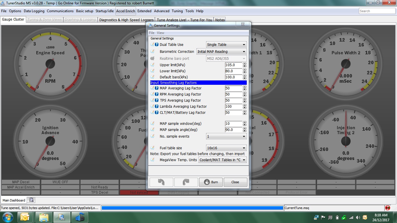
Changing the figures for the MS2 MAP Sampling settings, as suggested by Robert and Rod, resulted in some interesting, and I must admit for my part, unexpected results.
77 Clubman build thread
|
||||||
 12307 Posts Member #: 565 Carlos Fandango Burnham-on-Crouch, Essex |
7th Jan, 2018 at 08:00:38pm
just had a thought,
On 28th Aug, 2011 Kean said:
At the risk of being sigged... Joe, do you have a photo of your tool? http://www.turbominis.co.uk/forums/index.p...9064&lastpost=1 https://joe1977.imgbb.com/ |
||||||
|
6743 Posts Member #: 828 Post Whore uranus |
7th Jan, 2018 at 08:43:37pm
wow that made a bit of a difference . Medusa + injection = too much torque for the dyno ..https://youtu.be/qg5o0_tJxYM |
||||||
 (2)[/url] by [url=https://www.flickr.com/photos/150672766@N03/]Rod Sugden[/url], on Fli) 5988 Posts Member #: 2024 Formally Retired Rural Suffolk |
8th Jan, 2018 at 07:46:34am
Interesting observation Joe.
Schrödinger's cat - so which one am I ??? |
||||||
|
12307 Posts Member #: 565 Carlos Fandango Burnham-on-Crouch, Essex |
8th Jan, 2018 at 09:04:06am
Ah,
On 28th Aug, 2011 Kean said:
At the risk of being sigged... Joe, do you have a photo of your tool? http://www.turbominis.co.uk/forums/index.p...9064&lastpost=1 https://joe1977.imgbb.com/ |
||||||
|
604 Posts Member #: 1106 Post Whore Hungerford, Berks |
8th Jan, 2018 at 09:09:20am
Yes, I'm using the A version MPX4250.
77 Clubman build thread
|
||||||
|
8604 Posts Member #: 573 Formerly Axel Podland |
8th Jan, 2018 at 09:30:59am
More interesting data, thanks for posting. My analysis:
Edited by Paul S on 8th Jan, 2018. Saul Bellow - "A great deal of intelligence can be invested in ignorance when the need for illusion is deep."
|
||||||
|
5988 Posts Member #: 2024 Formally Retired Rural Suffolk |
8th Jan, 2018 at 10:16:57am
On 8th Jan, 2018 Joe C said:
Hmmm thats very interesting Rod, I hadnt considered that the Iox would'nt know crank position, I was planing to use one to measure stuff like TIP, but might have to rethink that. I think I'm right in saying that Joe, I'll wait for Jean to jump in if I'm wrong, but one thing he has pointed out regularly is the IOx cannot be used for anything that is engine timing critical because of the latency (delay) in the CanBus which is not a fixed delay so can't be calculated out. It sees all the basic MS data (like RPM) but I don't think it goes into much more detail. The delay is tiny and has never worried us for the kind of data we are logging because the logging frame rate between the MS2 and PC is way, way slower. Schrödinger's cat - so which one am I ??? |
||||||
|
12307 Posts Member #: 565 Carlos Fandango Burnham-on-Crouch, Essex |
8th Jan, 2018 at 10:21:10am
it looks like what they have done is extrapolated the average line out to where it would cross the 0 and 5v ponts, on the assumtion that the engiine is never going to hit these points.
On 8th Jan, 2018 Graham T said:
Yes, I'm using the A version MPX4250. The MAP calibration is set as default for the MPX4250 (from the pull down list): Value at 0.0Volts(%) = 10 Value at 5.0 Volts(%) = 260 Which seems not correct according to the data sheet? On 28th Aug, 2011 Kean said:
At the risk of being sigged... Joe, do you have a photo of your tool? http://www.turbominis.co.uk/forums/index.p...9064&lastpost=1 https://joe1977.imgbb.com/ |
||||||
|
5988 Posts Member #: 2024 Formally Retired Rural Suffolk |
8th Jan, 2018 at 10:33:10am
On 8th Jan, 2018 Joe C said:
it looks like what they have done is extrapolated the average line out to where it would cross the 0 and 5v ponts, on the assumtion that the engiine is never going to hit these points. On 8th Jan, 2018 Graham T said: Yes, I'm using the A version MPX4250. The MAP calibration is set as default for the MPX4250 (from the pull down list): Value at 0.0Volts(%) = 10 Value at 5.0 Volts(%) = 260 Which seems not correct according to the data sheet? I've just had a quick look at my project configuration - which is currently using a T-IOx rather than the full size one - and those values are what are coming up as the default in the T-IOx as well. So if they are out, they appear to be all out equally....... Schrödinger's cat - so which one am I ??? |
||||||
|
604 Posts Member #: 1106 Post Whore Hungerford, Berks |
8th Jan, 2018 at 10:47:26am
Actually, Ignore me.
77 Clubman build thread
|
||||||
|
604 Posts Member #: 1106 Post Whore Hungerford, Berks |
8th Jan, 2018 at 02:16:17pm
Thanks everyone for the feedback.
Edited by Graham T on 8th Jan, 2018. 77 Clubman build thread
|
||||||
|
6743 Posts Member #: 828 Post Whore uranus |
8th Jan, 2018 at 04:23:10pm
it does look like with a bit of jiggery pokery it will match the innovate most of the time . Medusa + injection = too much torque for the dyno ..https://youtu.be/qg5o0_tJxYM |
||||||
|
8604 Posts Member #: 573 Formerly Axel Podland |
8th Jan, 2018 at 05:12:55pm
A decent buffer on the signal line should sort it out.
Saul Bellow - "A great deal of intelligence can be invested in ignorance when the need for illusion is deep."
|
||||||
|
1267 Posts Member #: 831 Post Whore Montreal, Canada |
8th Jan, 2018 at 05:57:50pm
On 8th Jan, 2018 Rod S said:
On 8th Jan, 2018 Joe C said:
Hmmm thats very interesting Rod, I hadnt considered that the Iox would'nt know crank position, I was planing to use one to measure stuff like TIP, but might have to rethink that. I think I'm right in saying that Joe, I'll wait for Jean to jump in if I'm wrong, but one thing he has pointed out regularly is the IOx cannot be used for anything that is engine timing critical because of the latency (delay) in the CanBus which is not a fixed delay so can't be calculated out. It sees all the basic MS data (like RPM) but I don't think it goes into much more detail. The delay is tiny and has never worried us for the kind of data we are logging because the logging frame rate between the MS2 and PC is way, way slower. Rod, you are correct. You can't rely on a CAN bus message to compute a precise engine position and that's not just an IOx limitation but the nature of serial bus communication. A device needs to be directly connected to a crank sensor (or equivalent) to know the engine position. The IOx can see all the same data that TunerStudio can see but none of the internal ECU values or the raw sensor data. Jean |
||||||
| Home > A-Series EFI / Injection > EFI Testing - Dyno Day 6: 1.5:1 Ratio rockers | |||||||
|
|||||||


| Page: |