
| Page: |
| Home > A-Series EFI / Injection > MS2 Assembly Headache - Ignition drivers | |||||||
|
17 Posts Member #: 11671 Member |
7th Apr, 2018 at 01:41:39pm
Hi All,
|
||||||
|
17 Posts Member #: 11671 Member |
7th Apr, 2018 at 01:46:41pm
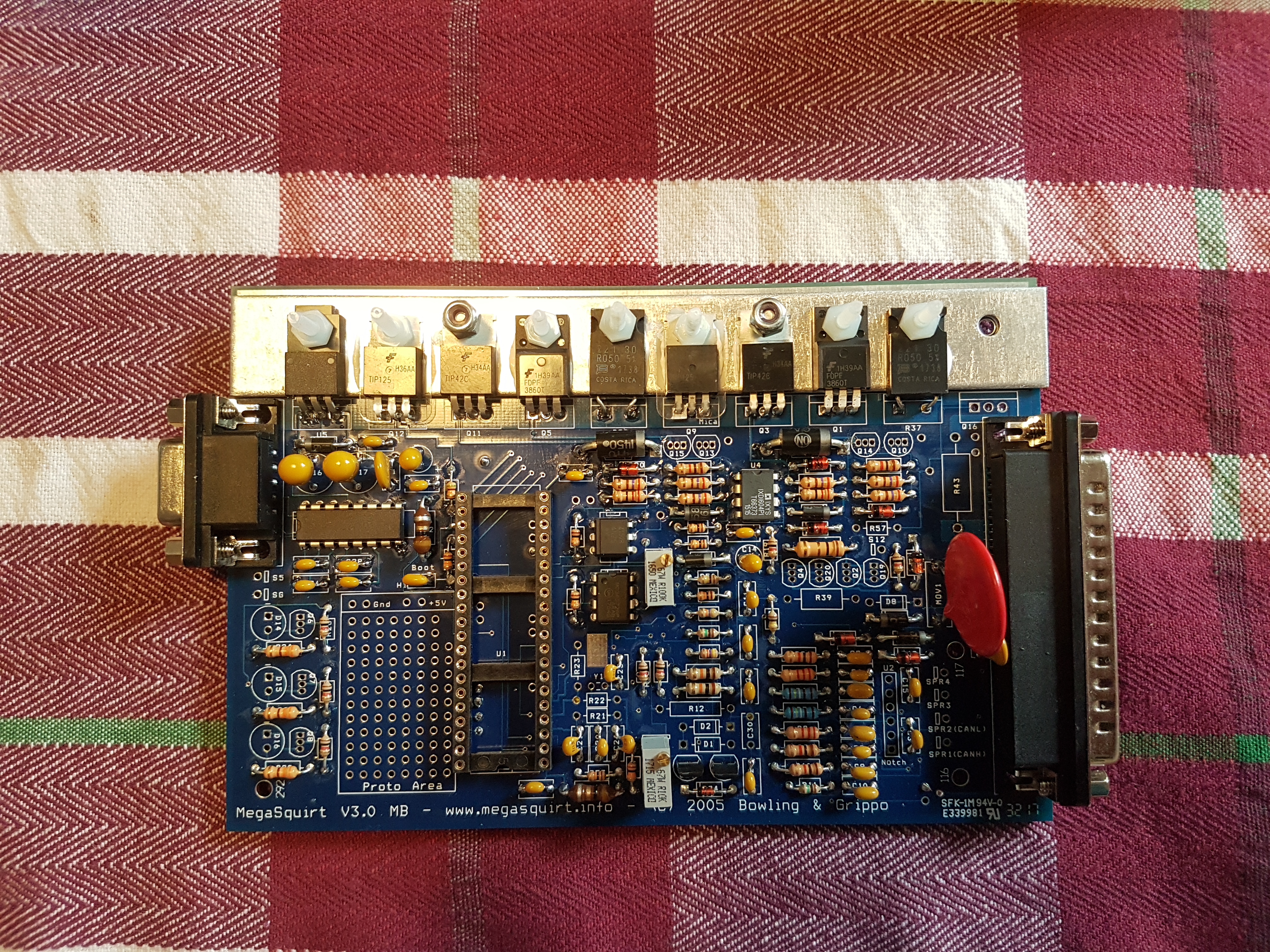
Attachments |
||||||
 (2)[/url] by [url=https://www.flickr.com/photos/150672766@N03/]Rod Sugden[/url], on Fli) 5988 Posts Member #: 2024 Formally Retired Rural Suffolk |
7th Apr, 2018 at 06:19:54pm
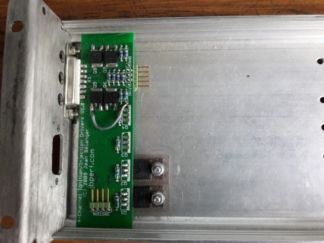
If you are using Jean's 4 channel board - not his Peak and Hold (P&H) board for low-z injectors but the one specifically for high-z injectors - then it includes the ignition drivers for up to 4 ignition channels.
Edited by Rod S on 8th Apr, 2018. Schrödinger's cat - so which one am I ??? |
||||||
|
17 Posts Member #: 11671 Member |
7th Apr, 2018 at 11:12:28pm
Hi Rod, thanks for your reply.
|
||||||
|
1267 Posts Member #: 831 Post Whore Montreal, Canada |
7th Apr, 2018 at 11:44:42pm
You don't need anything used for the injector drivers or the ignition driver. These are all the components on this schematics page: http://www.msextra.com/doc/pdf/html/MS2V30...re-3.4-170.html and the ignition driver components on the following page.
|
||||||
|
5988 Posts Member #: 2024 Formally Retired Rural Suffolk |
8th Apr, 2018 at 07:00:20am
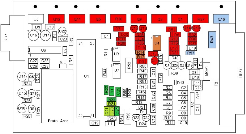
For future reference, here's a pictorial view that I did for someone a few years ago who was going to use Jean's 4 channel driver board, I've tidied it up a bit since I first did it (in case you come across it anywhere else) and you can cross reference it to the schematics Jean has mentioned.
Edited by Rod S on 8th Apr, 2018. Schrödinger's cat - so which one am I ??? |
||||||
|
17 Posts Member #: 11671 Member |
9th Apr, 2018 at 02:29:43pm
Hi guys, thanks for your replies, really appreciate it.
|
||||||
|
1267 Posts Member #: 831 Post Whore Montreal, Canada |
9th Apr, 2018 at 05:32:26pm
I'll put here the reply I sent to your email about the BOM. And maybe Rod has some recommendations about actual part numbers from a UK vendor.
|
||||||
|
5988 Posts Member #: 2024 Formally Retired Rural Suffolk |
9th Apr, 2018 at 07:51:04pm
I can give you Farnell (UK) part numbers for any of the parts used on the board, Farnell are probably best as they do free delivery to non-account holders for +£20 orders. RS similar pricing but I don't normally use them so I don't have a list of their numbers readily available.
Schrödinger's cat - so which one am I ??? |
||||||
|
17 Posts Member #: 11671 Member |
9th Apr, 2018 at 08:42:15pm
Hi Rod,
|
||||||
|
5988 Posts Member #: 2024 Formally Retired Rural Suffolk |
9th Apr, 2018 at 09:56:17pm
OK,
Schrödinger's cat - so which one am I ??? |
||||||
|
5988 Posts Member #: 2024 Formally Retired Rural Suffolk |
10th Apr, 2018 at 09:51:21am
IGBTs
Edited by Rod S on 11th Apr, 2018. Schrödinger's cat - so which one am I ??? |
||||||
|
1267 Posts Member #: 831 Post Whore Montreal, Canada |
10th Apr, 2018 at 05:30:33pm
The ISL9V5036 is what I used in the full kit and I've never had any issue reported on them. And you want to use a 1k resistor with them (R1-4). |
||||||
|
17 Posts Member #: 11671 Member |
11th Apr, 2018 at 05:03:59pm
Hi Everyone,
|
||||||
|
1267 Posts Member #: 831 Post Whore Montreal, Canada |
11th Apr, 2018 at 06:00:50pm
R5-8 are 1k resistors. |
||||||
|
1267 Posts Member #: 831 Post Whore Montreal, Canada |
11th Apr, 2018 at 06:09:45pm
I should add that the DB-15 connector I used on the board is this one: https://www.digikey.ca/products/en?keywords...171-015-102L011
Edited by jbelanger on 11th Apr, 2018. |
||||||
|
5988 Posts Member #: 2024 Formally Retired Rural Suffolk |
11th Apr, 2018 at 06:28:51pm
On 11th Apr, 2018 jbelanger said:
R5-8 are 1k resistors. Interesting Jean. I would have given the same answer based on the Microsquirt and MS3X schematics and the VND5N07 datasheet, but the board I have in front of me has 330R resistors. Not mine, I just inherited it as a dead board from an attempt to replace a failed VND5N07 which damaged a trace on the PCB, so I bridged the trace and added the plug connectors to do some testing (which went OK) but I wonder if the use of a 330R resistor was the root cause of the failure ? I don't know if the board was originally sourced as a kit or just a plain PCB (probably the latter). Schrödinger's cat - so which one am I ??? |
||||||
|
1267 Posts Member #: 831 Post Whore Montreal, Canada |
11th Apr, 2018 at 06:51:38pm
The goal in using 1k is mostly to make the driver as identical to the other MS drivers as possible and use something that agrees with the datasheet. A 330R resistor would probably increase switching speed somewhat but there is no way this would cause a failure in the trace you saw; it's still limiting current to 15mA at most with a 5V signal. |
||||||
|
5988 Posts Member #: 2024 Formally Retired Rural Suffolk |
11th Apr, 2018 at 07:30:00pm
The trace failure was nothing to do with the resistor value, it was just from a previous attempt to un-solder the failed VND5N07 (the soldering iron appears to have damaged the trace during removal)
Schrödinger's cat - so which one am I ??? |
||||||
|
1267 Posts Member #: 831 Post Whore Montreal, Canada |
11th Apr, 2018 at 07:42:12pm
I'm sorry, I misunderstood the origin of the failed trace.
|
||||||
|
17 Posts Member #: 11671 Member |
29th Apr, 2018 at 04:27:38pm
Hi All,
|
||||||
|
1267 Posts Member #: 831 Post Whore Montreal, Canada |
29th Apr, 2018 at 05:12:52pm
The ground on the DB15 goes to the car ground. The ground pin on the driver board goes to the MS board ground so the proto area ground is a good choice.
|
||||||
|
5988 Posts Member #: 2024 Formally Retired Rural Suffolk |
30th Apr, 2018 at 06:24:28am
On 29th Apr, 2018 Nobby said:
I am using a ford coil pack with wasted spark so do I need to connect the ignition header to the main board? Or can i use the ignition drivers on the main board? The standard mainboard, even if fully assembled, only has one high voltage/current ignitor (Q16). To run wasted spark on any "dumb" coilpack (like the EDIS one) you use two ignitors - two of the locations on Jean's board in this case - and connect them to D14 and D16 as per the manual (the manual will say to connect via resistors but they're already on Jean's board). The settings in TunerStudio for wasted spark take care of swapping the CPU outputs to make D14 and D16 the ignition outputs in the correct sequence. I'm out this morning but I'll do a photo later of how I did it (the other half of the case to my photo above). Schrödinger's cat - so which one am I ??? |
||||||
|
17 Posts Member #: 11671 Member |
2nd May, 2018 at 06:44:48pm
Hi Guys,
|
||||||
|
1267 Posts Member #: 831 Post Whore Montreal, Canada |
2nd May, 2018 at 07:32:32pm
You need to connect them to R32 and R36 respectively as per this picture on my web site: http://www.jbperf.com/sequential/v3_0_inj_outputs.png It is also in the MS2/Extra manual but the resolution is bad there.
|
||||||
| Home > A-Series EFI / Injection > MS2 Assembly Headache - Ignition drivers | |||||||
|
|||||||
| Page: |