
| Page: |
| Home > Show Us Yours! > Efi Supercharged Blow Through | |||||||
 1648 Posts Member #: 9038 Post Whore Carlisle, Cumbria |
30th Jul, 2018 at 03:08:54pm
There was once a mini in one of the mags that had a polo gti engine in it, which had the radiator underneath |
||||||
|
76 Posts Member #: 8976 Advanced Member |
30th Jul, 2018 at 07:50:46pm
Hi its been like that for the last 7 years and i never had over heating problems, considering that we have a very hot climate in Malta
On 30th Jul, 2018 jonny f said:
Impressive. Will be interesting to see if it gets enough air flow under there. Great ideas. |
||||||
 2091 Posts Member #: 9894 Post Whore Dorking |
1st Aug, 2018 at 10:23:08pm
Thats excellent!
On 30th Jul, 2018 turbominik said:
Hi its been like that for the last 7 years and i never had over heating problems, considering that we have a very hot climate in Malta On 30th Jul, 2018 jonny f said: Impressive. Will be interesting to see if it gets enough air flow under there. Great ideas. |
||||||
|
76 Posts Member #: 8976 Advanced Member |
15th Aug, 2018 at 09:31:31pm
Hi a bit more update today I finished the intake pipes and the bypass valve pipe.
Edited by turbominik on 16th Aug, 2018. |
||||||
|
744 Posts Member #: 7912 Post Whore Australia oi oi oi! |
21st Sep, 2018 at 10:09:23pm
very nice |
||||||
 4890 Posts Member #: 1775 Post Whore Chester |
22nd Sep, 2018 at 05:57:21am
All looking very neat I run a supercharger and I don't care the TB is on the wrong side.
|
||||||
 967 Posts Member #: 3228 Post Whore North of the Netherlands |
22nd Sep, 2018 at 02:39:51pm
Very nice package Dazed and Confused.... |
||||||
|
76 Posts Member #: 8976 Advanced Member |
2nd Oct, 2018 at 08:44:40pm
Hi, its been a long time since I done some updates on the project but i was waiting for some items that I ordered. First of all thanks for all the nice comments on the project.
|
||||||
|
166 Posts Member #: 8952 Advanced Member Athens Greece |
14th Oct, 2018 at 07:12:37am
Looking good, keep it up. Almost there.
|
||||||
|
76 Posts Member #: 8976 Advanced Member |
26th Oct, 2018 at 08:42:12pm
Hi all some updates on the wiring, so far most of the wiring under the dash is almost complete. Ignition switch, indicators switch and wiper switch are ready epas is ready and i started to the plugs for the gauges.
|
||||||
|
76 Posts Member #: 8976 Advanced Member |
22nd Nov, 2018 at 09:55:40pm
Hi a little update the fuse box is ready the ecu connection are also ready and finally started the wiring on the engine.
Edited by turbominik on 24th Nov, 2018. |
||||||
|
76 Posts Member #: 8976 Advanced Member |
4th Dec, 2018 at 09:18:32pm
Hi finally the wiring is done |
||||||
|
76 Posts Member #: 8976 Advanced Member |
11th Dec, 2018 at 09:57:51pm
Hi finally the engine is all assembled.
Edited by turbominik on 13th Dec, 2018. |
||||||
|
76 Posts Member #: 8976 Advanced Member |
26th Dec, 2018 at 09:41:33pm
Hi today I finished to fit the wheel speed sensor for the speedometer and the epas ecu.
|
||||||
|
76 Posts Member #: 8976 Advanced Member |
26th Jan, 2019 at 11:20:16pm
Hi the speed sensor is ready and functioning well.
Edited by turbominik on 28th Jan, 2019. |
||||||
|
76 Posts Member #: 8976 Advanced Member |
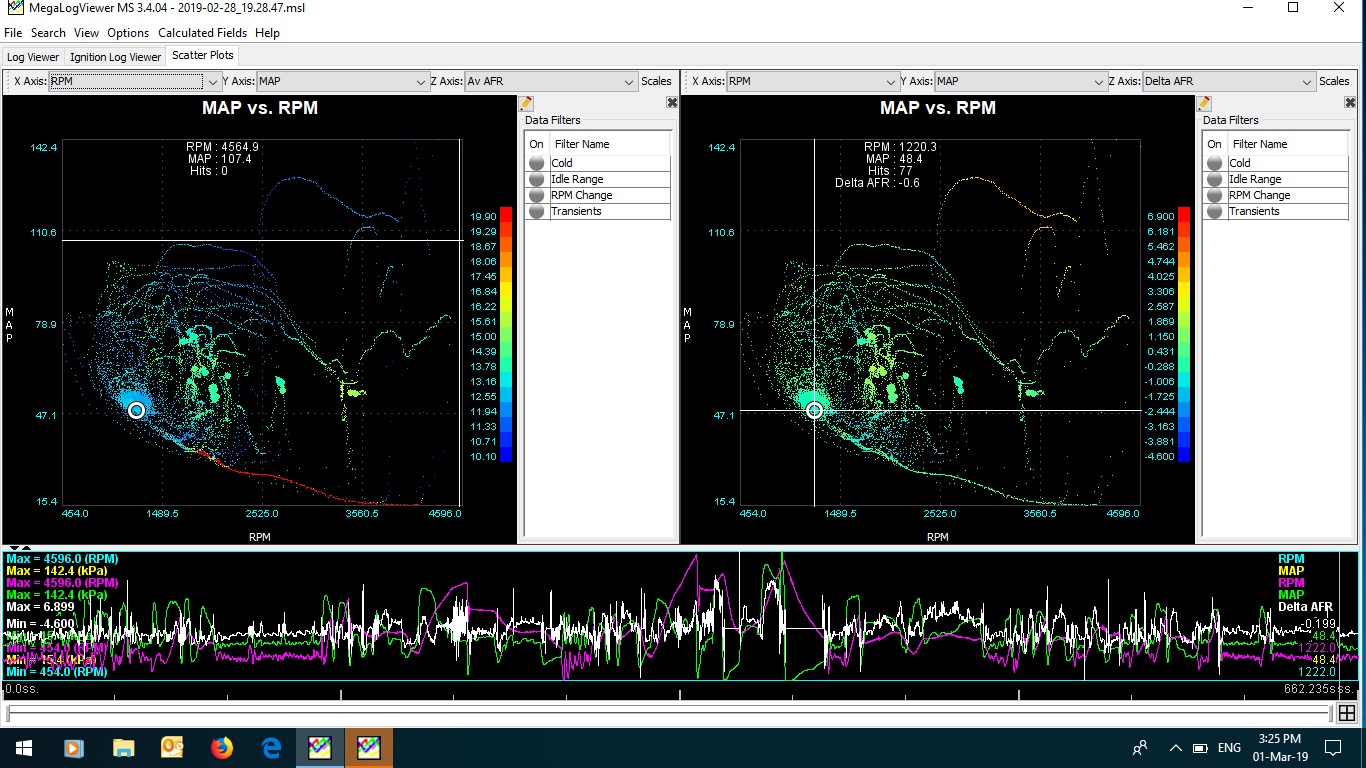
28th Feb, 2019 at 10:54:53pm
Hi I attached a log and the current tune since I'me having trouble with the mixture balance between inner and outer. I'me using the two pulse system (each injector is connected to 2 drivers)
|
||||||
|
76 Posts Member #: 8976 Advanced Member |
28th Feb, 2019 at 10:55:09pm
Hi I'me having a problem to upload the log file and the tune how can I upload them
Edited by turbominik on 1st Mar, 2019. |
||||||
|
76 Posts Member #: 8976 Advanced Member |
1st Mar, 2019 at 09:19:56am
Hi these are the links for the files
|
||||||
|
8604 Posts Member #: 573 Formerly Axel Podland |
1st Mar, 2019 at 10:51:59am
How have you setup the injector timing?
Edited by Paul S on 3rd Mar, 2019. Saul Bellow - "A great deal of intelligence can be invested in ignorance when the need for illusion is deep."
|
||||||
|
76 Posts Member #: 8976 Advanced Member |
1st Mar, 2019 at 02:25:38pm
On 1st Mar, 2019 Paul S said:
How have you setup the injector timing? I've not used the 2 pulse method yet, basically because I'm happy with single pulse. This is the timing table for my lads NA 998 which is in regular use: 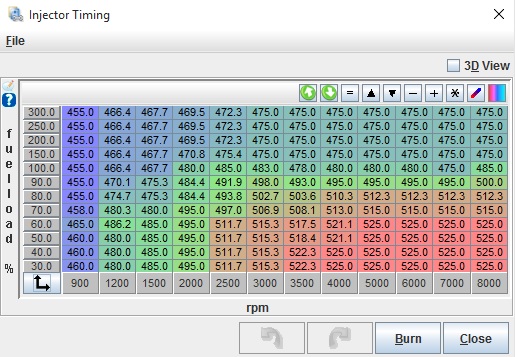
This is based on single pulse, mid pulse timing, so it delivers the fuel around TDC. Hence, if you add 90 degrees from all the values, it should deliver fuel mid-stroke. You will need to set up tables for both primaries and secondaries. Can you run the engine without boost? Only it would be ideal to get the primaries sorted first before moving onto the secondaries. |
||||||
|
8604 Posts Member #: 573 Formerly Axel Podland |
1st Mar, 2019 at 04:51:52pm
Right, I have now looked at the files.
Edited by Paul S on 1st Mar, 2019. Saul Bellow - "A great deal of intelligence can be invested in ignorance when the need for illusion is deep."
|
||||||
|
76 Posts Member #: 8976 Advanced Member |
1st Mar, 2019 at 06:27:55pm
Yes I got it close as possible without trim but worst part is bellow 3500rpms then it's start to equalize as it gains more revs.
|
||||||
|
8604 Posts Member #: 573 Formerly Axel Podland |
1st Mar, 2019 at 07:24:44pm
On 1st Mar, 2019 turbominik said:
As for injection since the injectors are wired according to the firing order, if the injector is injecting on the outer open valve the next injection is 540 deg after on the inner open valve if I'm not wrong. That is true. It the assumption that your timing is delivering to the outer cylinder that is under question. However, having thought about it some more, you must be doing just that else most the fuel would be going into the inners. I assume that you are using mid pulse timing? Saul Bellow - "A great deal of intelligence can be invested in ignorance when the need for illusion is deep."
|
||||||
|
76 Posts Member #: 8976 Advanced Member |
1st Mar, 2019 at 08:34:25pm
I'm using beginning of squirt but I used the other two options but with the same results. I will reset the fuel trim to 0 and try to advance more the timing, do you think that if i add 180 degrees to the existing map will help to balance the mixtures? |
||||||
|
8604 Posts Member #: 573 Formerly Axel Podland |
3rd Mar, 2019 at 10:34:52am
I suggested adding 180 degrees to your injection timing as it is much lower than mine for single pulse, whereas I would expect it to be only slightly lower. Try it, but it may not work very well. At least you can verify that all is happening as it should.
Edited by Paul S on 3rd Mar, 2019. Saul Bellow - "A great deal of intelligence can be invested in ignorance when the need for illusion is deep."
|
||||||
| Home > Show Us Yours! > Efi Supercharged Blow Through | |||||||
|
|||||||


 next is step is to assemble the intake and exhaust manifold with new gaskets.


| Page: |