
| Page: |
| Home > A-Series EFI / Injection > Calibrating and Testing Coolant Sensors | |||||||
|
186 Posts Member #: 7637 Advanced Member Fremont California |
11th Oct, 2018 at 11:05:57pm
I have not posted in awhile, but I still check in from time to time.
|
||||||
|
1267 Posts Member #: 831 Post Whore Montreal, Canada |
11th Oct, 2018 at 11:26:11pm
With the sensor only, you will always get the same voltage as what you're powering it with. To get a varying voltage, you need a bias resistor (a resistor between 5V and the sensor). But to get the voltage from a temperature table (I assume you have a table of temperature vs voltage at ECU connector) you need to know what the resistance value is for the bias resistor used inside the ECU.
|
||||||
|
186 Posts Member #: 7637 Advanced Member Fremont California |
12th Oct, 2018 at 01:18:07am
Thank you Jean I knew I was missing something. I was hoping to do some tests to check the table provided. The same sensor was used in MGF engines and the tables I have seen for those are different than the version provided in SXTune.
Edited by tmsmini on 13th Oct, 2018. |
||||||
|
186 Posts Member #: 7637 Advanced Member Fremont California |
12th Oct, 2018 at 01:54:55am
This MGF site has a full table with voltage and resistance values.
|
||||||
 (2)[/url] by [url=https://www.flickr.com/photos/150672766@N03/]Rod Sugden[/url], on Fli) 5988 Posts Member #: 2024 Formally Retired Rural Suffolk |
12th Oct, 2018 at 05:06:46am
Schrödinger's cat - so which one am I ??? |
||||||
|
186 Posts Member #: 7637 Advanced Member Fremont California |
12th Oct, 2018 at 09:25:27pm
Thank you for your comments. I will do some resistance testing today.
|
||||||
|
3596 Posts Member #: 655 Post Whore Northern Ireland |
12th Oct, 2018 at 10:02:35pm
The only surefire way to do this...is calibrate it yourself.
Edited by stevieturbo on 12th Oct, 2018. 9.85 @ 145mph
|
||||||
|
1267 Posts Member #: 831 Post Whore Montreal, Canada |
12th Oct, 2018 at 11:20:31pm
On 12th Oct, 2018 stevieturbo said:
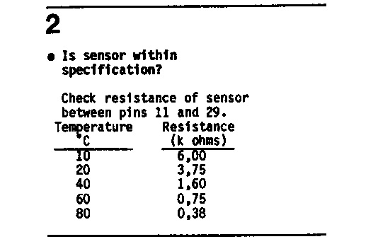
The only surefire way to do this...is calibrate it yourself. Have the sensor plugged into the ecu, reading temperatures or voltages etc on the ecu...then making direct comparisons against a good known accurate temp gauge...be it a thermometer or other known calibrated means of reading temperature. ie stick sensor in some water in a pan along with the thermometer and heat gently, and plot your own readings. any other way involves guesses or assumptions. While using the ECU and a correctly measured temperature at the sensor will obviously yield the best results, using other methods does not necessarily involve guesses or assumptions (unless that's what you call using known physical properties and their associated equations). If the ECU is a complete black box then you don't have much of a choice but to make the aforementioned measurements. But if you know the input circuit (bias resistor) and can measure the sensor resistance at 3 temperatures as mentioned by Rod then you can completely define the temperature vs voltage curve for the sensor. You will still have some error due to the tolerance of the different ECU components and from your measurements. By the way, even the direct temperature measurement using the ECU will have some error due to the temperature measurement from whatever thermometer you use and how you make the measurement. |
||||||
|
186 Posts Member #: 7637 Advanced Member Fremont California |
13th Oct, 2018 at 01:47:31am
While watching my pot boil, I did some searching and found this one too from a few years ago:
Edited by tmsmini on 13th Oct, 2018. |
||||||
|
186 Posts Member #: 7637 Advanced Member Fremont California |
13th Oct, 2018 at 02:43:23am
Just realized Darren did all his work with the fahrenheit scale.
Edited by tmsmini on 13th Oct, 2018. |
||||||
|
186 Posts Member #: 7637 Advanced Member Fremont California |
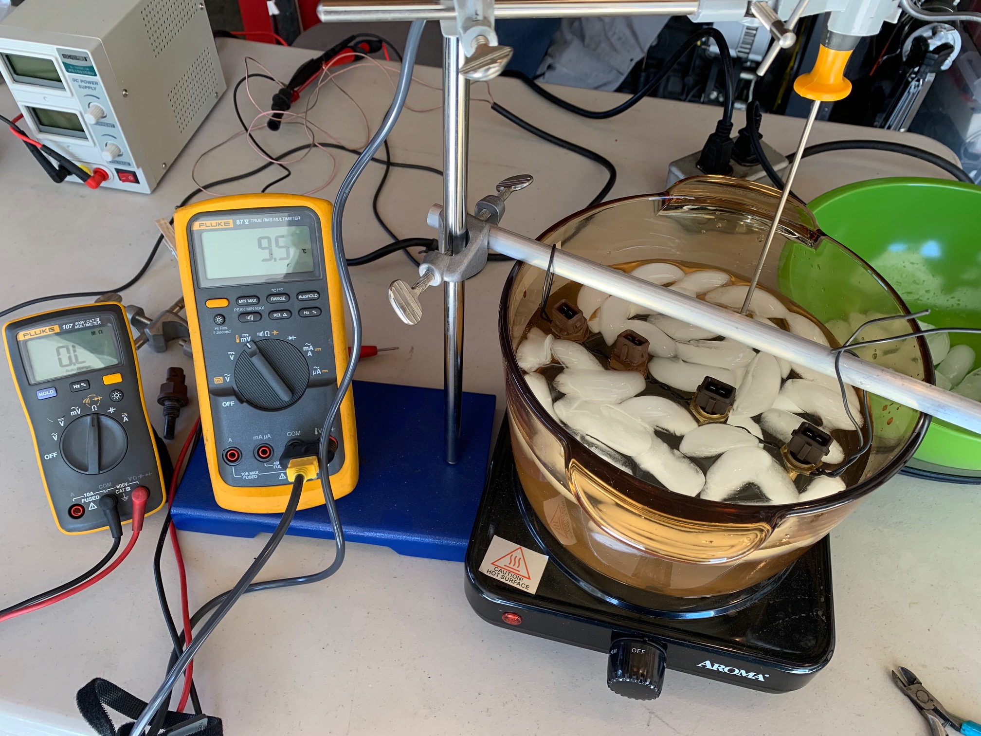
13th Oct, 2018 at 02:52:25am
Not the best test setup, but it worked.
|
||||||
|
3596 Posts Member #: 655 Post Whore Northern Ireland |
13th Oct, 2018 at 11:48:57pm
Different ecu's will use different internal pullup resistors. Screw formulas, test properly, as installed connected to the ecu. 9.85 @ 145mph
|
||||||
|
5988 Posts Member #: 2024 Formally Retired Rural Suffolk |
14th Oct, 2018 at 12:57:03pm
On 13th Oct, 2018 stevieturbo said:
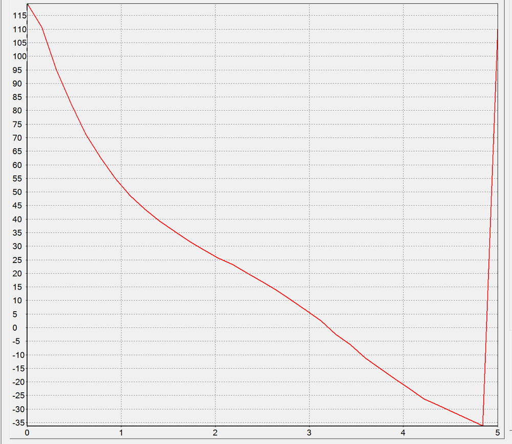
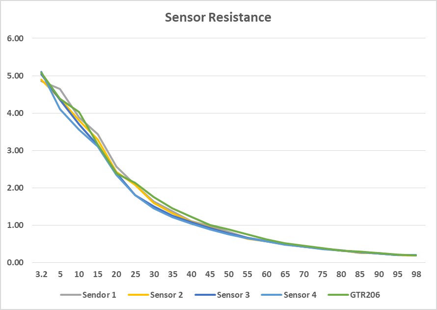
Different ecu's will use different internal pullup resistors. Screw formulas, test properly, as installed connected to the ecu. It's a bias resistor, not a "pullup", it creates a potential divider to measure a voltage off an NTC resistor. No "pullup" about it. And if you want to "screw formulas" how do you think any ECU can get a voltage that actually represents temperature without using the formula ??? Do any of the graphs above look like a straight line ????? Maybe you should try Specsavers ??? Schrödinger's cat - so which one am I ??? |
||||||
|
3596 Posts Member #: 655 Post Whore Northern Ireland |
14th Oct, 2018 at 09:55:01pm
On 14th Oct, 2018 Rod S said:
On 13th Oct, 2018 stevieturbo said:
Different ecu's will use different internal pullup resistors. Screw formulas, test properly, as installed connected to the ecu. It's a bias resistor, not a "pullup", it creates a potential divider to measure a voltage off an NTC resistor. No "pullup" about it. And if you want to "screw formulas" how do you think any ECU can get a voltage that actually represents temperature without using the formula ??? Do any of the graphs above look like a straight line ????? Maybe you should try Specsavers ??? What on earth does a straight line have to do with anything ? And where did I say anything about a straight line ? And yes it is a pullup resistor, as it effectively ties the 5v reference to the input "pulling up" that to an apparent 5v, which the sensor which is then tied to reference ground is attached to, and where the "voltage" is created which the ecu uses. Some may call this by different names, but when it comes to ecu's and automotive wiring, the term pullup is common and correct. And yes, if you do not know the resistance inside the ecu...then formulas are useless ! 9.85 @ 145mph
|
||||||
|
1267 Posts Member #: 831 Post Whore Montreal, Canada |
14th Oct, 2018 at 11:57:48pm
The term pullup might be common but it is definitely not correct in that case. A pullup is used for pulling up a signal to a specific level (a logic 5V or 3.3V for example) which is not what you want here because you want a varying voltage. It may look similar on a diagram but it is different from a bias resistor.
Edited by jbelanger on 14th Oct, 2018. |
||||||
|
5988 Posts Member #: 2024 Formally Retired Rural Suffolk |
16th Oct, 2018 at 05:27:21pm
On 14th Oct, 2018 stevieturbo said:
What on earth does a straight line have to do with anything ? And where did I say anything about a straight line Stevie, you said "screw the formulas". If it's not a straight line it needs a formula. That's what ECUs are quite good at doing, maths..... The equation is quite straightforward but it's not a straight line where you say "screw the formula" On 14th Oct, 2018 stevieturbo said:
And yes it is a pullup resistor, as it effectively ties the 5v reference to the input "pulling up" that to an apparent 5v, which the sensor which is then tied to reference ground is attached to, and where the "voltage" is created which the ecu uses. No, it's not, try to understand the difference between a pullup - 0-5V logic like a hall switch - and a bias resistor - any thing between 0V and 5V so giving an ADC of quite high resolution rather than just zero or one. On 14th Oct, 2018 stevieturbo said:
And yes, if you do not know the resistance inside the ecu...then formulas are useless ! Again you miss the point. The formula is "inside" the ECU. If you want to calibrate the thermistor, measure its resistance at varying temperatures and use an ECU which wants to know the resistance for its calibration. The voltages generated are only posted on the internet for people fault finding or people who don't understand how the physics and maths works. Schrödinger's cat - so which one am I ??? |
||||||
|
3596 Posts Member #: 655 Post Whore Northern Ireland |
16th Oct, 2018 at 11:33:30pm
It doesnt need a formula if you test/calibrate as I described.
On 14th Oct, 2018 jbelanger said:
The term pullup might be common but it is definitely not correct in that case. A pullup is used for pulling up a signal to a specific level (a logic 5V or 3.3V for example) And you are doing exactly that....pulling up that input line to "5v" in order for there to be a voltage present to create the signal from the resistive sensor. It is rare that a 5v reference be applied to a sensor and the input line sees the outcome from that. Some very old ecu's may have done it that way, but it is not common. 9.85 @ 145mph
|
||||||
|
1267 Posts Member #: 831 Post Whore Montreal, Canada |
17th Oct, 2018 at 12:57:40am
On 16th Oct, 2018 stevieturbo said:
And you are doing exactly that.... No. Read what Rod says. I don't know if you're intentionally dismissing what others are saying because you need to feel you're right or if you're really misunderstanding the term and concept. In either case, I'm done with this because you're not helping with the original questions or with any useful information. Edited by jbelanger on 17th Oct, 2018. |
||||||
| Home > A-Series EFI / Injection > Calibrating and Testing Coolant Sensors | |||||||
|
|||||||

| Page: |