
| Page: |
| Home > Help Needed / General Tech Chat > K1100 breather setup | |||||||
|
33 Posts Member #: 6004 Member Portsmouth |
14th Mar, 2019 at 01:49:11pm
Looking for some help with the K1100 breather setup.
|
||||||
|
33 Posts Member #: 6004 Member Portsmouth |
14th Mar, 2019 at 02:55:12pm
Ok, a little correction. Just had another look at the transfer case hole and whilst it doesnt look to have an opening to let the engine breath, I tried giving it the kiss of life and tried blowing into it and its not a dead end.
|
||||||
 2646 Posts Member #: 1246 Post Whore Lowestoft, Suffolk. |
14th Mar, 2019 at 08:36:03pm
. Edited by shane on 14th Mar, 2019. |
||||||
|
2646 Posts Member #: 1246 Post Whore Lowestoft, Suffolk. |
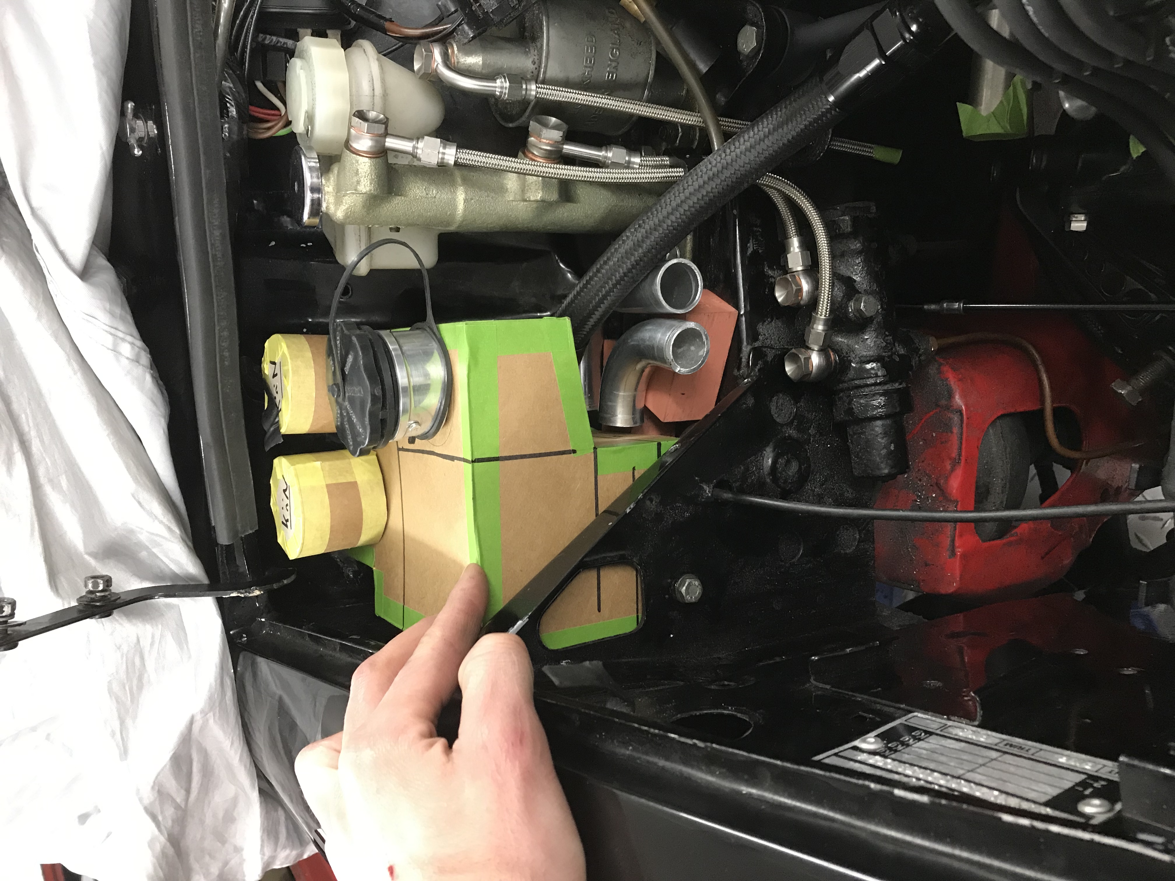
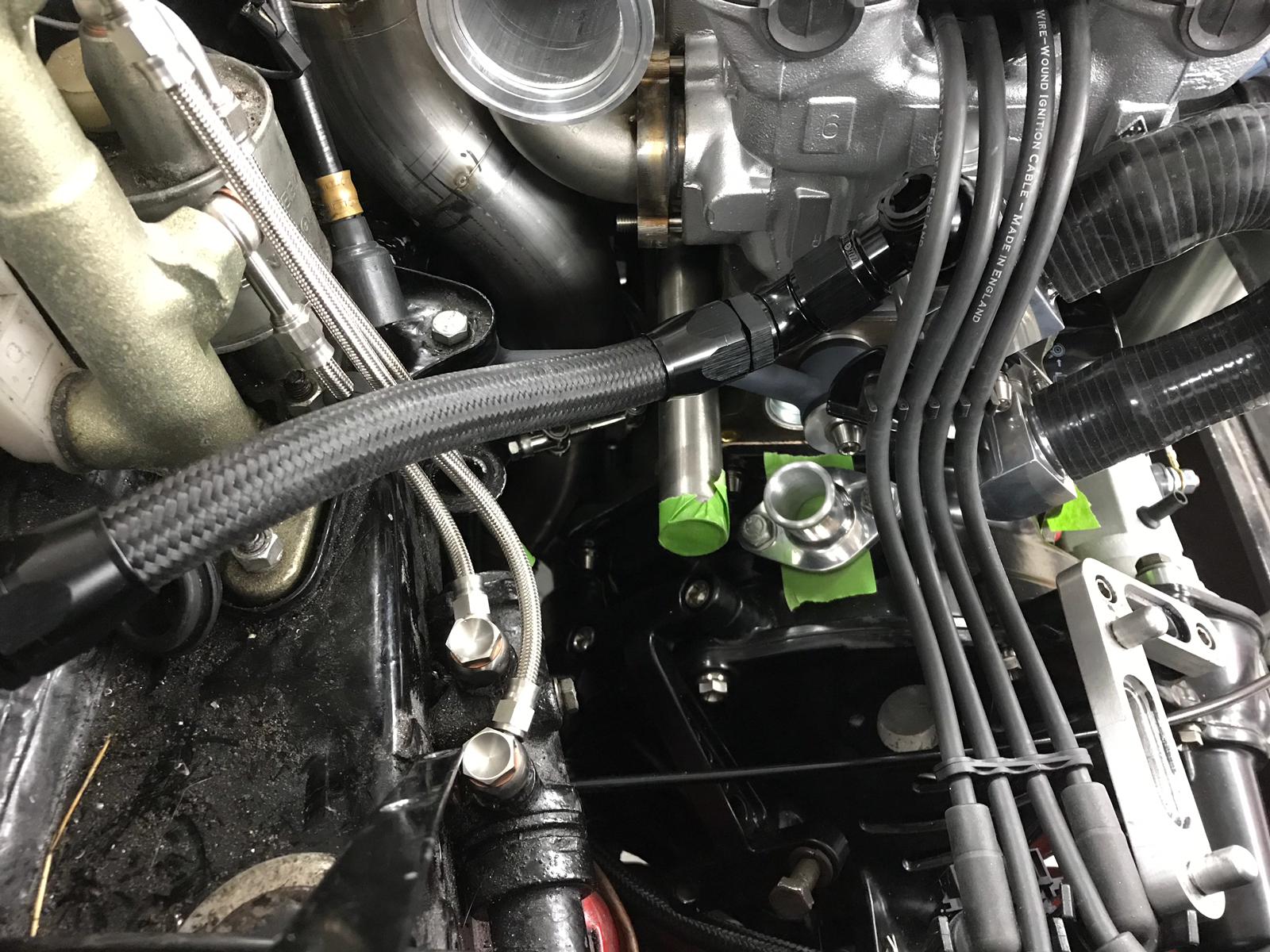
14th Mar, 2019 at 08:55:43pm
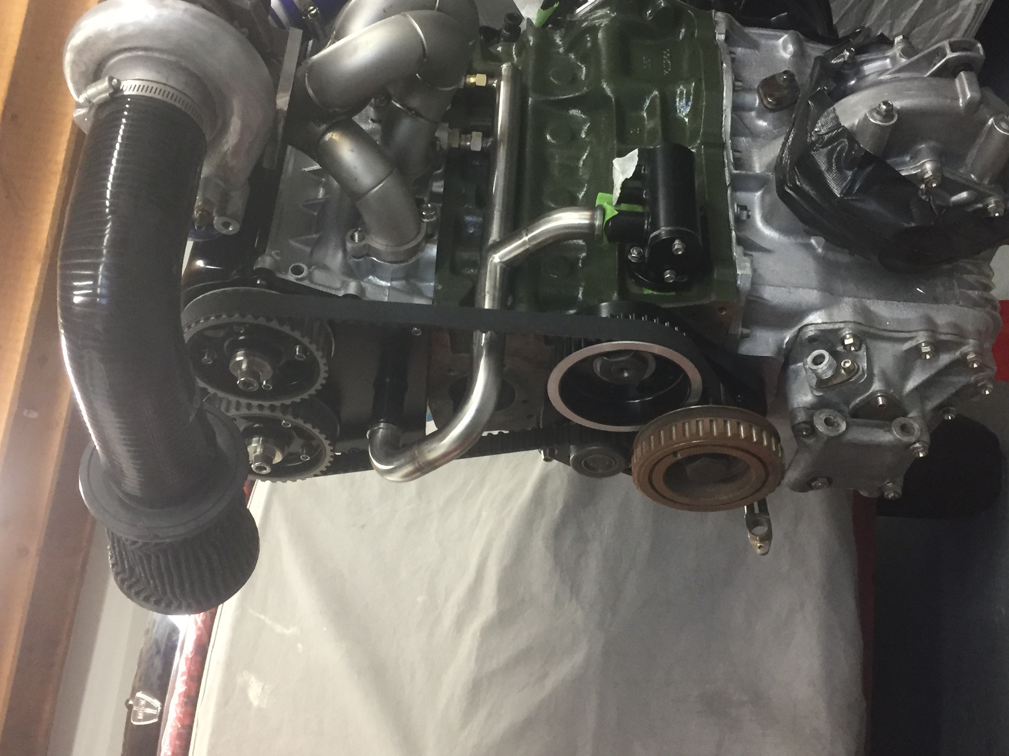
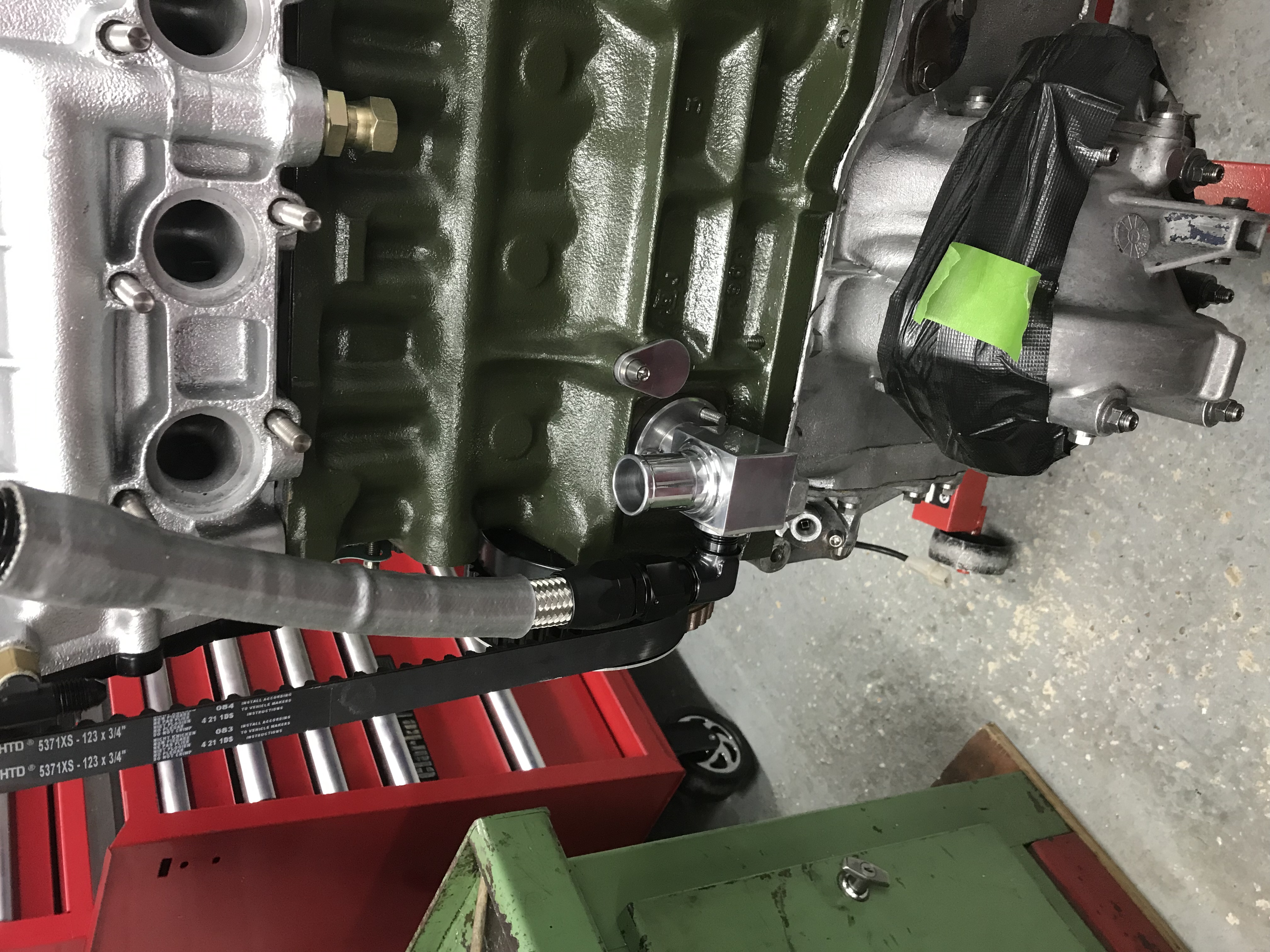
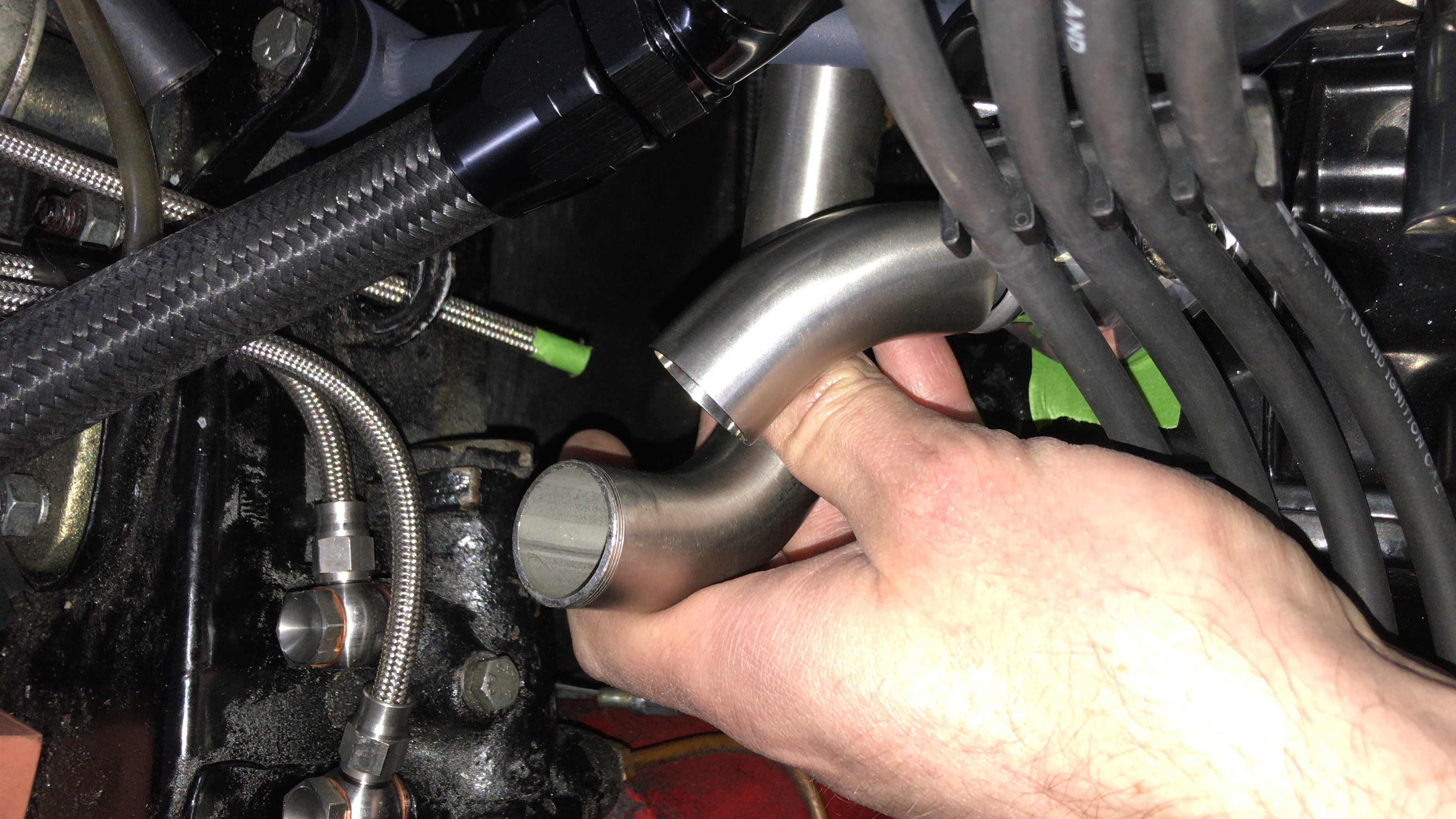
Right hope this makes it easier to see/understand what I’ve tried to achieve.
Edited by shane on 15th Mar, 2019. |
||||||
 2406 Posts Member #: 341 aka T2clubby South Staffs |
14th Mar, 2019 at 10:03:15pm
That looks bloody tidy Shane |
||||||
|
2646 Posts Member #: 1246 Post Whore Lowestoft, Suffolk. |
14th Mar, 2019 at 10:35:10pm
Thanks Kean, the whole build has been made 3 times.
|
||||||
 5417 Posts Member #: 6181 Double hard bastard brookwood woking |
14th Mar, 2019 at 10:57:02pm
On 14th Mar, 2019 shane said:
Thanks Kean, the whole build has been made 3 times. Shane I am looking forward to getting started on my 16v now tbh. I have started posting on Instagram also my name on there is turbomk1golf
On 1st Nov, 2007 Ben H said:
There is no such thing as 'insignificant weight saving', it all adds up. |
||||||
|
2646 Posts Member #: 1246 Post Whore Lowestoft, Suffolk. |
14th Mar, 2019 at 11:28:18pm
I’ll be glad to get it finished, 10 years is taking the p@@s now.
On 14th Mar, 2019 madmk1 said:
On 14th Mar, 2019 shane said:
Thanks Kean, the whole build has been made 3 times. Shane I am looking forward to getting started on my 16v now tbh. |
||||||
|
33 Posts Member #: 6004 Member Portsmouth |
14th Mar, 2019 at 11:42:45pm
Thanks Shane for your help and explanation.
|
||||||
|
2646 Posts Member #: 1246 Post Whore Lowestoft, Suffolk. |
15th Mar, 2019 at 12:14:04am
Not a problem,
On 14th Mar, 2019 Shiner said:
Thanks Shane for your help and explanation. Just so I can understand, you have run the drain from the head to the block mounted at the fuel pump location and then T'd it off and extended it to a separate breather catch tank which also the crankcase breather goes to? This sounds achievable, although making that catch tank would be difficult with my welding skills, can I just leave it in cardboard form 
Thanks Shane. Edited by shane on 15th Mar, 2019. |
||||||
|
33 Posts Member #: 6004 Member Portsmouth |
15th Mar, 2019 at 12:34:01am
Perfect, makes sense. Thank you again.
|
||||||
|
2646 Posts Member #: 1246 Post Whore Lowestoft, Suffolk. |
15th Mar, 2019 at 09:31:38am
Thanks,
|
||||||
 1030 Posts Member #: 1291 Post Whore Suffolk / Birmingham |
15th Mar, 2019 at 10:22:17am
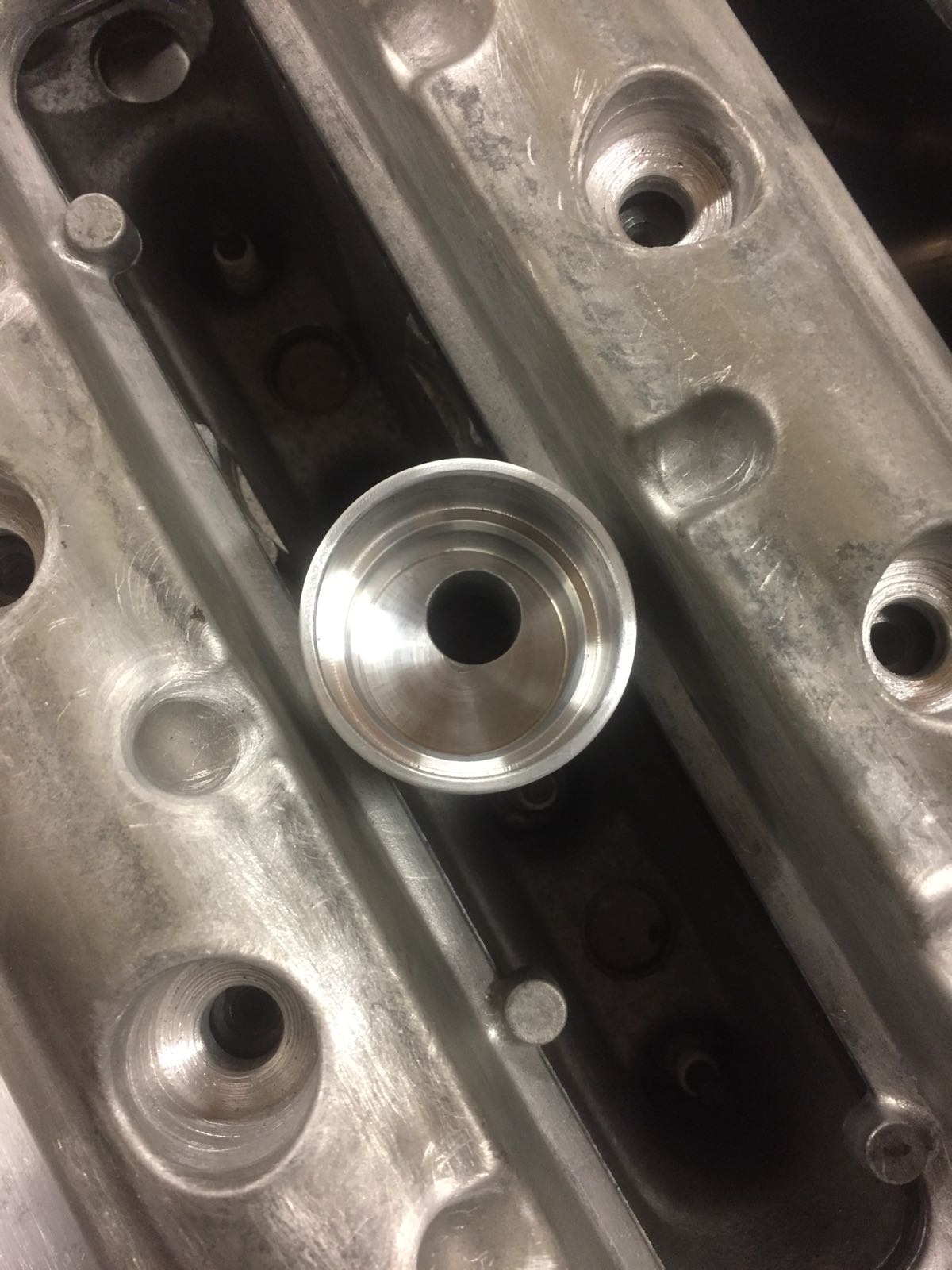
The block they sell that goes on the fuel pump hole is for the oil drains from the head. You dont want to breath from there as there's too much oil flying about.
|
||||||
|
33 Posts Member #: 6004 Member Portsmouth |
15th Mar, 2019 at 11:34:37am
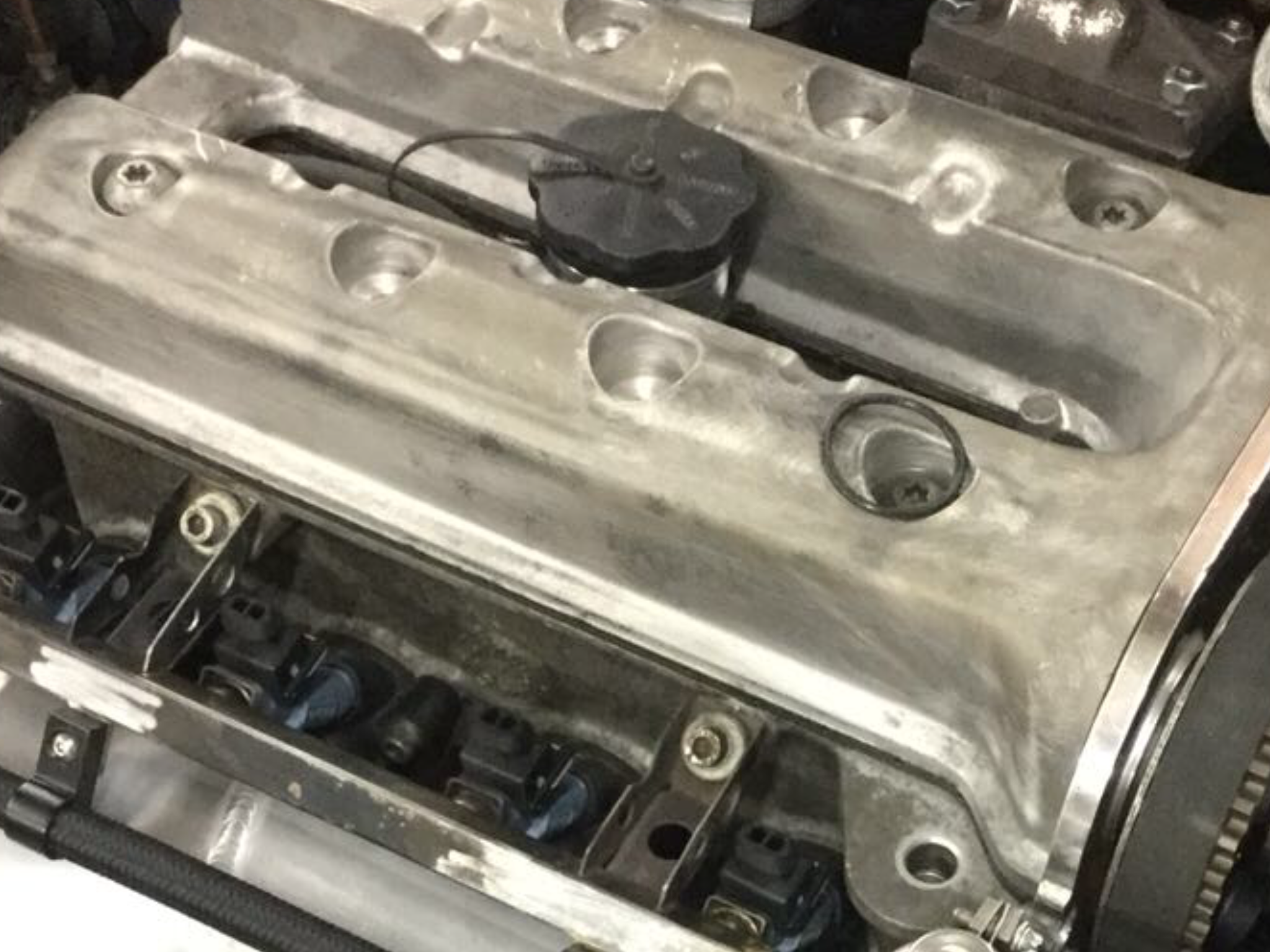
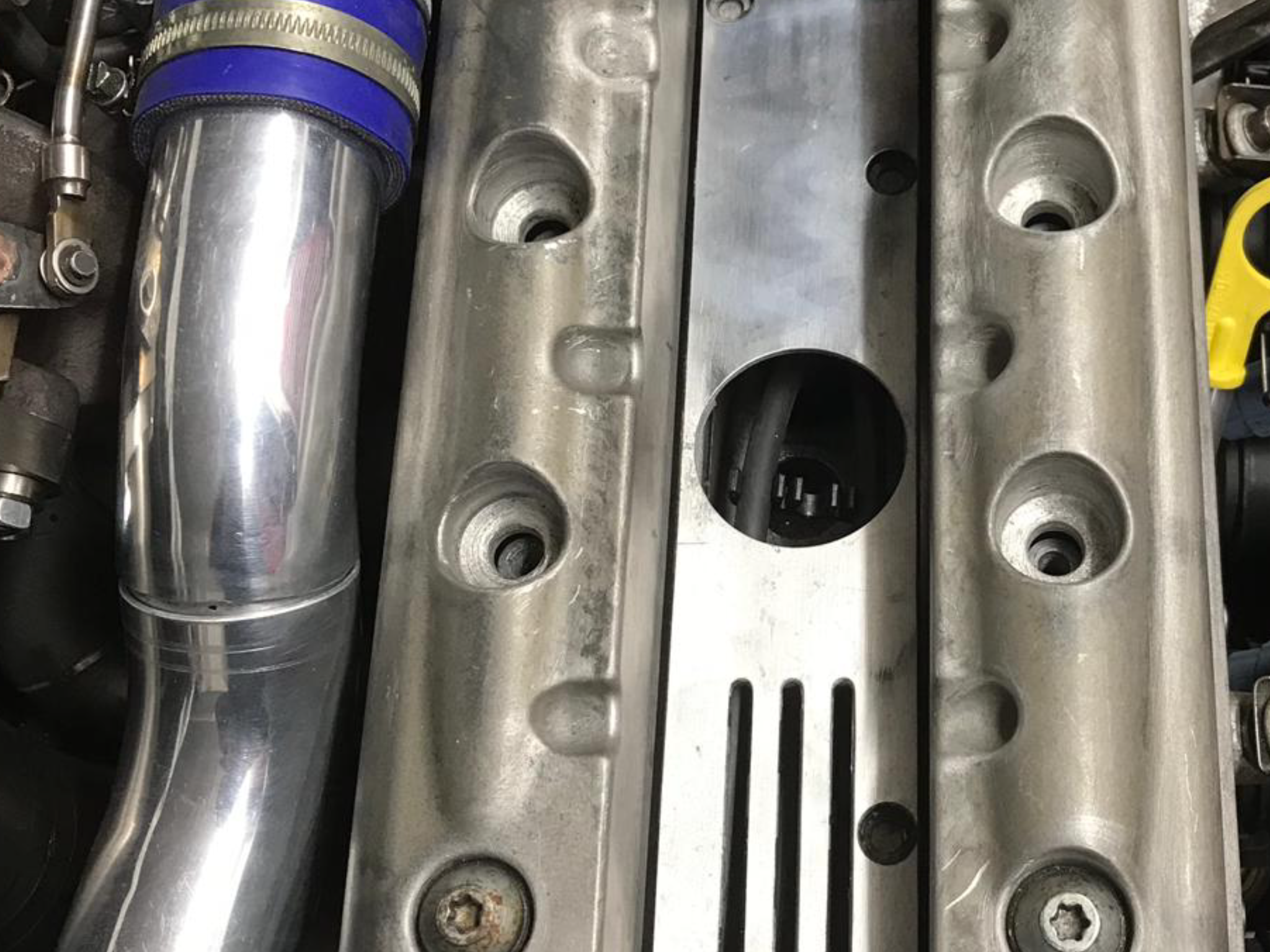
Could you fill with oil through the dizzy hole or is that hard to get to. Been ages since I've seen my engine in the mini itself?
|
||||||
|
2646 Posts Member #: 1246 Post Whore Lowestoft, Suffolk. |
15th Mar, 2019 at 11:54:18am
I can see that, but that said there has been previous comment on here within other breather related threads that there is a lot of oil flying about around the transfer case breather with the drop gears located below, also I think it was Joe C mentioned once that a lot of oil gets flung out of the dizzy hole if open with the engine running but that hasn’t stopped people using either as breather point successfully.
On 15th Mar, 2019 slater said:
The block they sell that goes on the fuel pump hole is for the oil drains from the head. You dont want to breath from there as there's too much oil flying about. Simply take a large breather from the transfer housing and a small one from the top breather outlet on the end of the head. Noting else is needed. You can also fill oil though the transfer housing. By far the neatest solution. http://www.turbominis.co.uk/forums/index.php?p=vt&tid=610404 Interesting read. Shane Edited by shane on 15th Mar, 2019. |
||||||
| Home > Help Needed / General Tech Chat > K1100 breather setup | |||||||
|
|||||||


| Page: |