|
Home > Show Us Yours! > Supercharged and injected imp, allowed?
|
blown_imp

223 Posts
Member #: 598
Senior Member
Gaol
|
|
Day 13 – average really!
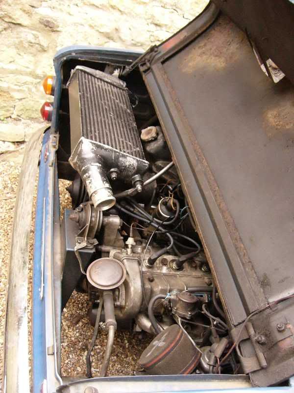
Well today has been pretty normal really, I have finished the right hand intercooler mount, so the intercooler is steady back and forth. The left hand intercooler mount had been fabricated, and this steadies it at the required angle. The intercooler inlet was shortened, and drilled for the left had mount. I have removed the pulley from the supercharger, and readied it for the fitting of the blower pulley.
The upper section of the mount was the part added today, this is jolly strong as when pulled the entire car goes up and down!
The join can be seen at the top of this photo
The whole extra part added today can be seen at the top of the photo.
This is the left hand mount, it is attached through the inlet pipe, and to the left hand chassis leg.
This is the intercooler all in and mounted, super!
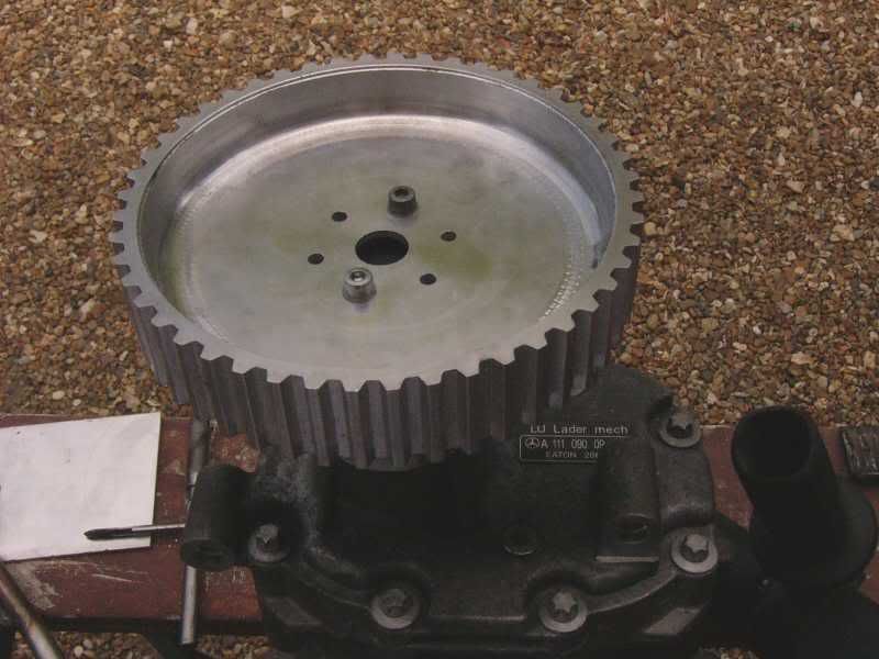
This is the original Mercedes pulley, I ground back the corner and then hacksawed through it all the way around.
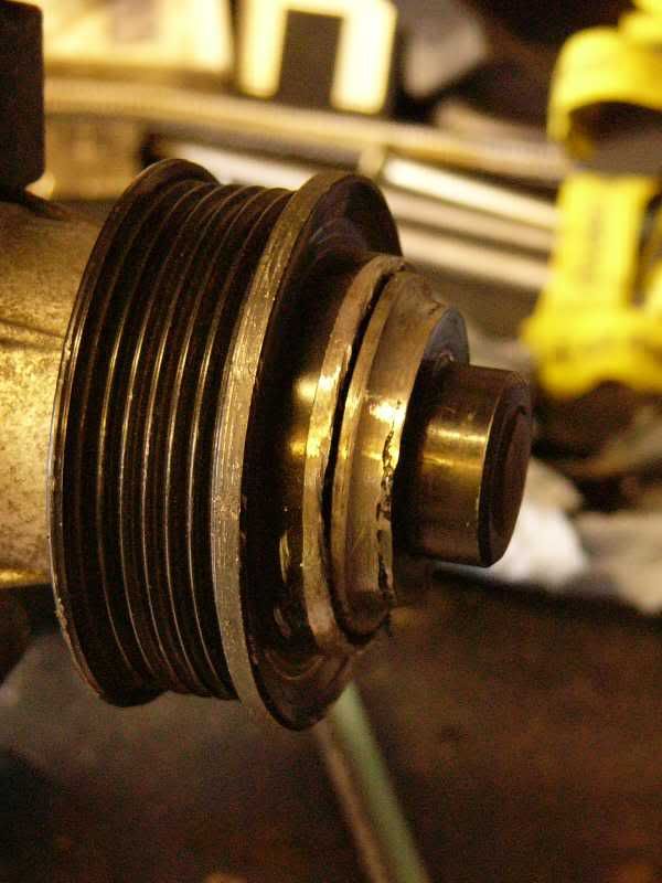
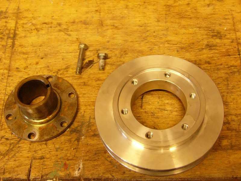
The pulley was removed and the edge cleaned up, the new pulley will mount to the flange face that is left. The flange is 8mm steel so it should be fine to mount to!
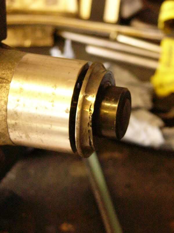
This is the pulley placed on the end of the shaft, the flange will have to be drilled and tapped to take 6 M5 bolts.
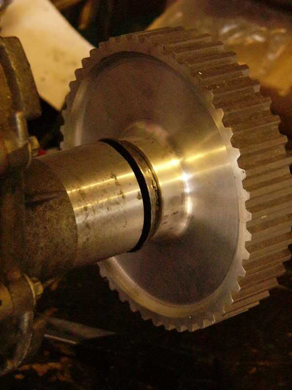
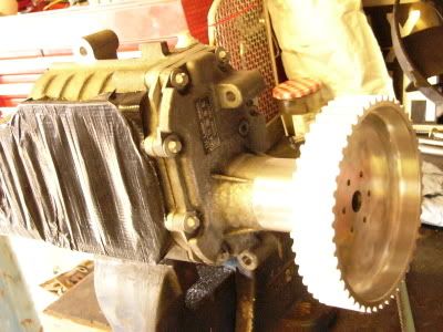
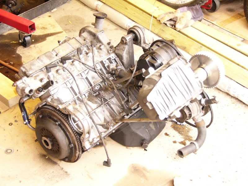
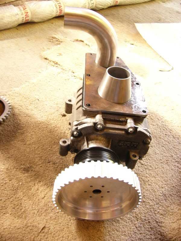
The whole blower with the pulley ready to be fitted into the S4 imp 
Tomorrow I will be making up the blower mount, again lots of fabrication just like the intercooler mount. This one is a little more critical for straightness though, if it isn’t totally straight then the belt will continually come off, NOT good  I think that I am going to put the blower pulley on the engine, and on the blower its self, then put some thick box steel clamped on the two faces so they are parallel. It will stay clamped like this until the whole frame is made, I really hope it works! I think that I am going to put the blower pulley on the engine, and on the blower its self, then put some thick box steel clamped on the two faces so they are parallel. It will stay clamped like this until the whole frame is made, I really hope it works!
More tomorrow guys and gals
J
Day 14 – Sherlaaaaaam!
Well last night it came to me in a dream, I realised how I could chop my springs, flatten the ends and not affect the tempering. No joke I had to get up at 4.30am and write it down!
When it was really time to get up I jumped into the lowering head first, I had a spare set of lowering springs just in case it didn’t work so I had nothing to lose. I removed the stock front springs and proceeded to chop them down with the grinder.
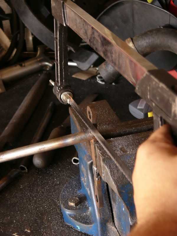
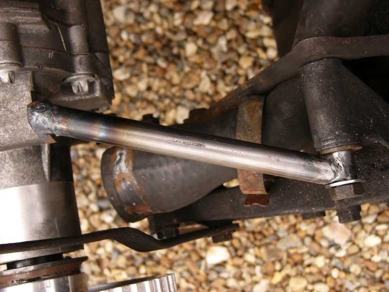
Then for the flattening of the ends, I needed to heat the bar to cherry red, but not let the heat travel down the metal to ruin the tempering. I had just the item to do this, my TIG welder creates a very high heat but only in a concentrated area, I heated the spring end in three places at 90 degrees to each other and compressed it downward. I left it in between applying the heat so as to not let it build up.
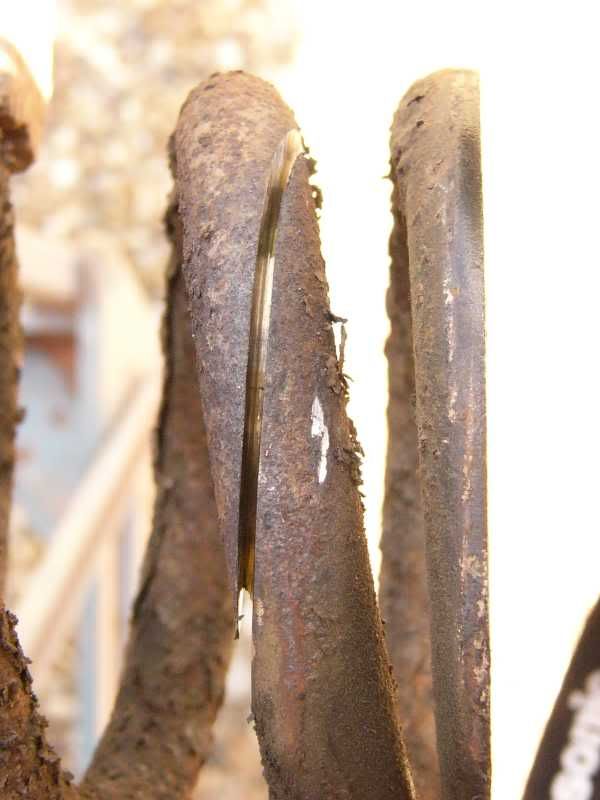
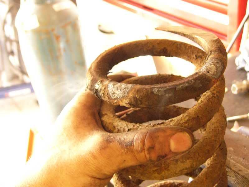
Here I am holding the spring immediately after heating just a few centimetres away, the heat was all concentrated just where the bend was created, the rest of the spring should be fine!
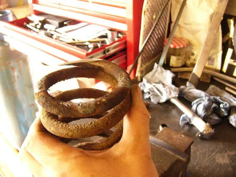
Here is my lowered spring next to a ‘montecarlo’ lowering spring, the monte is 1” lower than stock, so mine is around 2 – 2.5” lower.
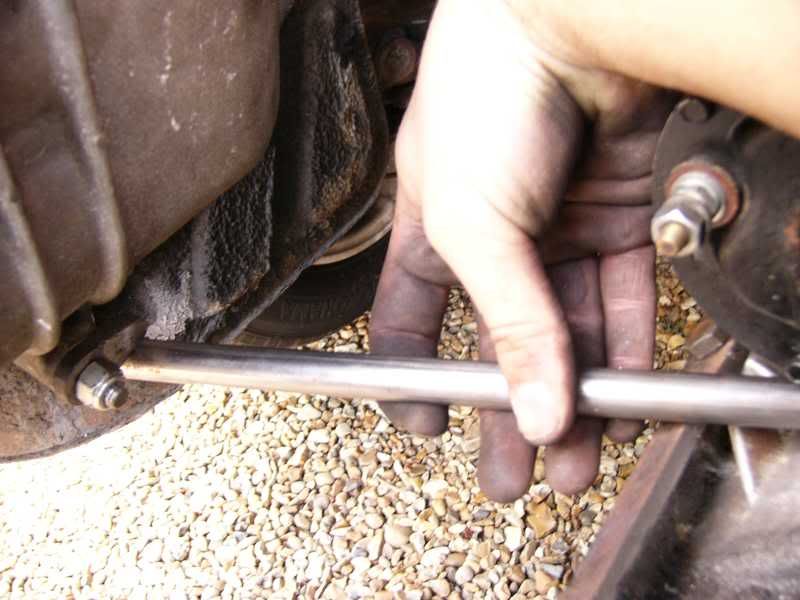
The process was repeated for the rear springs, here I am holding one just after ehating, the smoke is still rising!
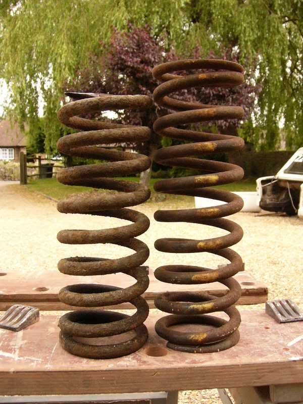
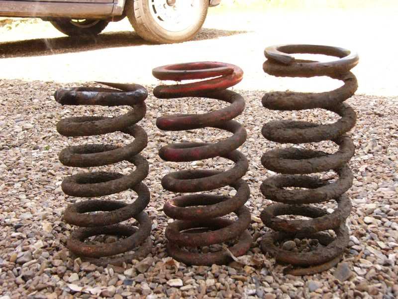
Here is a stock rear spring on the right, the central is a ‘montecarlo’ spring, and the left is my spring.
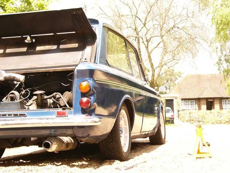
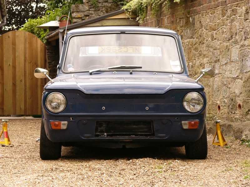
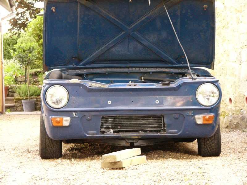
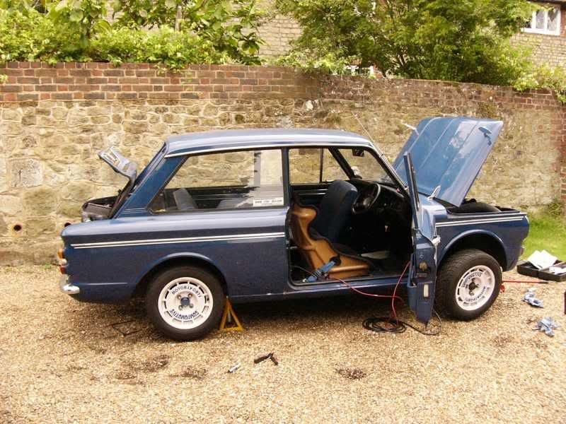
This is the car with just the front springs in
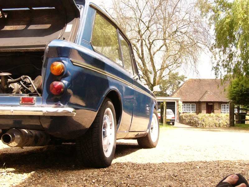
And with both front and rear springs
Here it is from the front, it seems a little stiffer than normal now as well, a result from chopping?
Looks like I’ve got to start to sort out the camber tomorrow!
Next on the list was the supercharger mount, I have started to cut and file some more 5mm plate for the mounts on the block, this mount will be fully triangulated for maximum stiffness. I’m jolly concerned about this mount, to get it strong enough, and stiff enough to perform correctly.
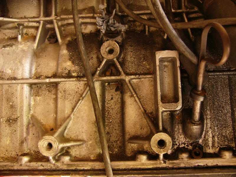
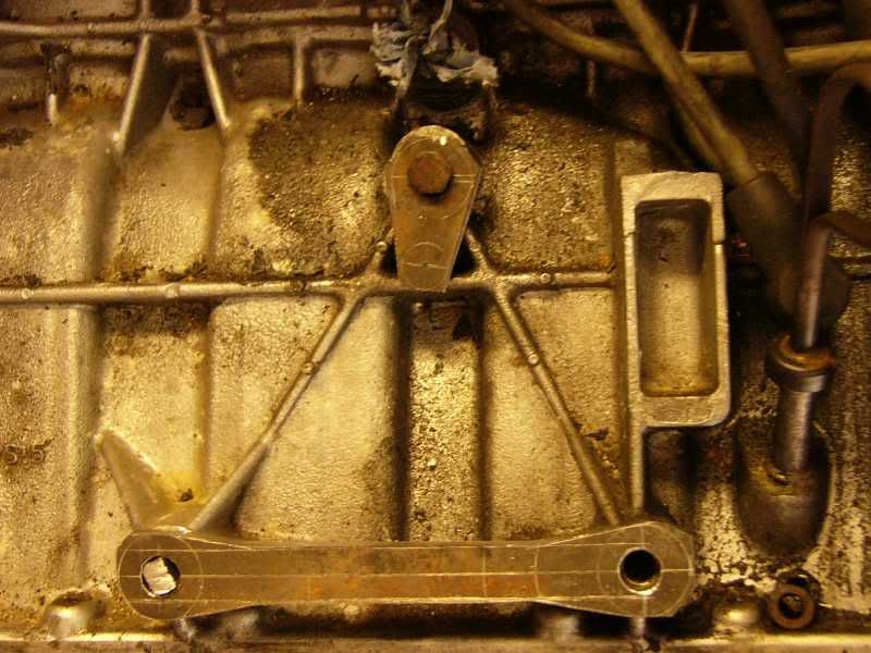
Here is the block mounts, this is where the engine is mounted to the chassis when in a Talbot sunbeam, should be strong enough!
I marked out this dog bone shape to mount two tubes to the bottom of the blower, these will then be triangulated to the top mount and the top mount will also go to the blower.
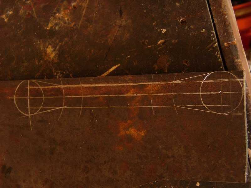
Here is it cut out and semi profiled to shape, I will continue filing this tomorrow, it takes some time!
That’s it for today, pretty good one really, I’m jolly happy, especially with the stance of the car, looks super duper
Tomorrow I will finish the engine blower mounts, then the flanges for the actual blower itself will be fabricated. I will also be sorting out the kingpins for less camber on the front wheels and fitting the new front wishbones, then I can think about the disk kit too, GO GO GO!
J
On 5th of Sep, 2006 at 05:47pm mini13 said:
I reckon if his brains were gunpowder he couldn't blow his own hat off...
|
Tom Fenton
Site Admin

15302 Posts
Member #: 337
Fearless Tom Fenton, Avon Park 2007 & 2008 class D winner & TM legend.
Rotherham South Yorkshire
|
|
Interesting stuff!
On 29th Nov, 2016 madmk1 said:
On 28th Nov, 2016 Rob Gavin said:
I refuse to pay for anything else
Like fuel 😂😂
|
Jackman
695 Posts
Member #: 984
Post Whore
Westhoughton, Bolton
|
|
This is a great topic, Days are flying by.
Manchester Minis
|
Joe C

12307 Posts
Member #: 565
Carlos Fandango
Burnham-on-Crouch, Essex
|
|
Whats the blower from?
On 28th Aug, 2011 Kean said:
At the risk of being sigged...
Joe, do you have a photo of your tool?
http://www.turbominis.co.uk/forums/index.p...9064&lastpost=1
https://joe1977.imgbb.com/
|
blown_imp
223 Posts
Member #: 598
Senior Member
Gaol
|
|
Yeah im posting about 4 days a day, if you see what i mean?
The blower is from a mercedes 230 kompressor, pretty usedfull with the inlet and outlet on the same side. Its a eaton M45 so the same as a new mini, just with earier to fabricate inlet and outlet.
J
On 5th of Sep, 2006 at 05:47pm mini13 said:
I reckon if his brains were gunpowder he couldn't blow his own hat off...
|
Vegard
7765 Posts
Member #: 74
I pick holes in everything..Chief ancient post excavator
Norway
|
|
I like what you're doing, but lowering a car like that is just stupid. Thw springs become so brittle, they'll crack whenever you don't expect them to.
Hazardous bodging it is. What do the historic racers use?
On 13th Jul, 2012 Ben H said:
Mine gets in the way a bit, but only when it is up. If it is down it does not cause a problem.
|
blown_imp
223 Posts
Member #: 598
Senior Member
Gaol
|
|
Why do you think they will crack? heating of the spring removed the tempering that is orginally put into it, this actually causes the spring to become more malleable and LESS lightly to crack.
I was very careful to heat the psrings in such a way as to contain the heat within as smaller are as possible. Cutting springs is normally done using a gas axe, this puts a huge amount of heat into the spring removing the heat treatments orginally provided causing them to collapse.
Also this isnt the final solution, its to test height and ride quality so i can decide on the spring rate when i swap to coilovers.
I dont just jump into these things without thinking about it, im a degree qualified engineer and ive got a pretty good idea on metallurgy.
I appreciate your concens all the same.
Cheers
J
Edited by blown_imp on 2nd Nov, 2006.
On 5th of Sep, 2006 at 05:47pm mini13 said:
I reckon if his brains were gunpowder he couldn't blow his own hat off...
|
blown_imp
223 Posts
Member #: 598
Senior Member
Gaol
|
|
Day 15 – Fight fight fight!
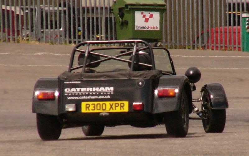
Well yesterday I went out for my graduation present, learning how to drift in a caterham 7! Super duper fun, I came second out of 21, considering that I’ve never done any performance driving its not too bad!

I also got my degree mark today, I am now James Hill Beng Hons Motorsport Engineering, I got a 2:1 so I’m jolly happy!
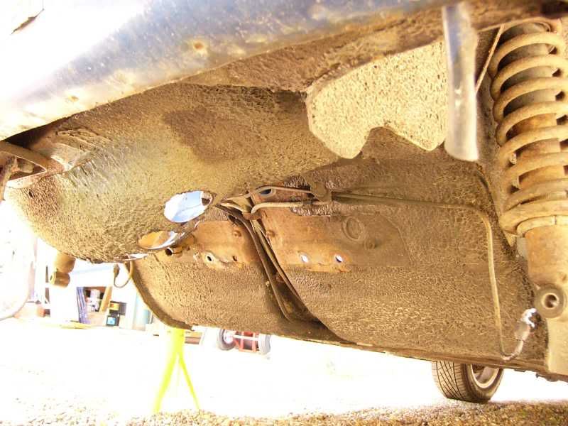
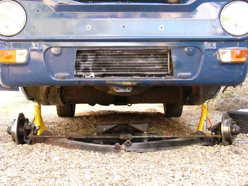
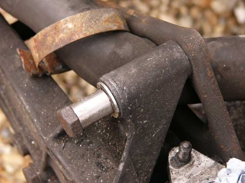
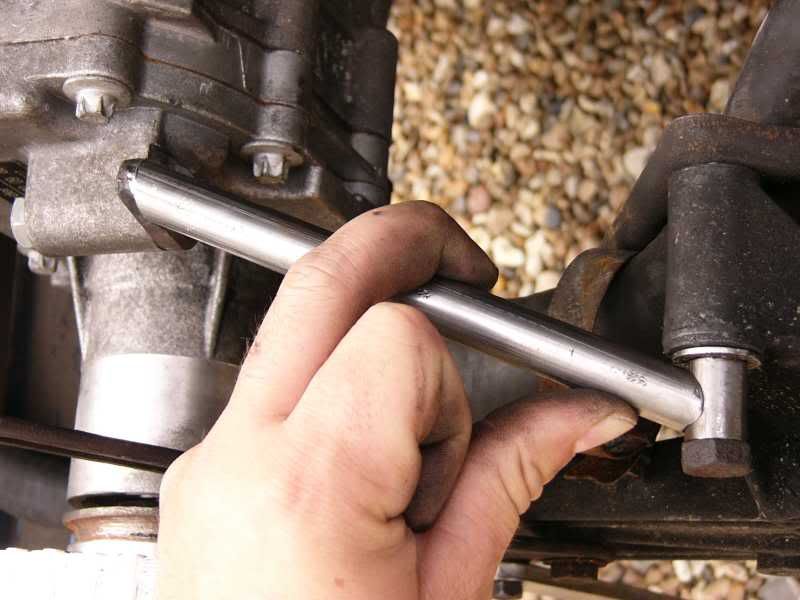
As for the car progress today has had a few up and downs, this morning I was fuming at the stupid car (silly little bitch!), it is jolly old and so nothing is easy to get off. I needed to change the front wishbones and suspension, but I ended up taking everything off the front of the car, mega headache! I even had to take the rear mounting plate off too, as the bolts would only come off if this is removed aswell, stupid rootes designers :( . Also one of the bolts was rusted to a bush so that was proper stuck, I ended up cutting it and pulling the whole thing out, was proper shitty! After removing the old wishbones I realised why I needed to put new ones on –
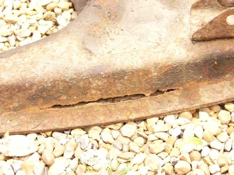
Uh oh that was lucky! The hole is about 5” long!
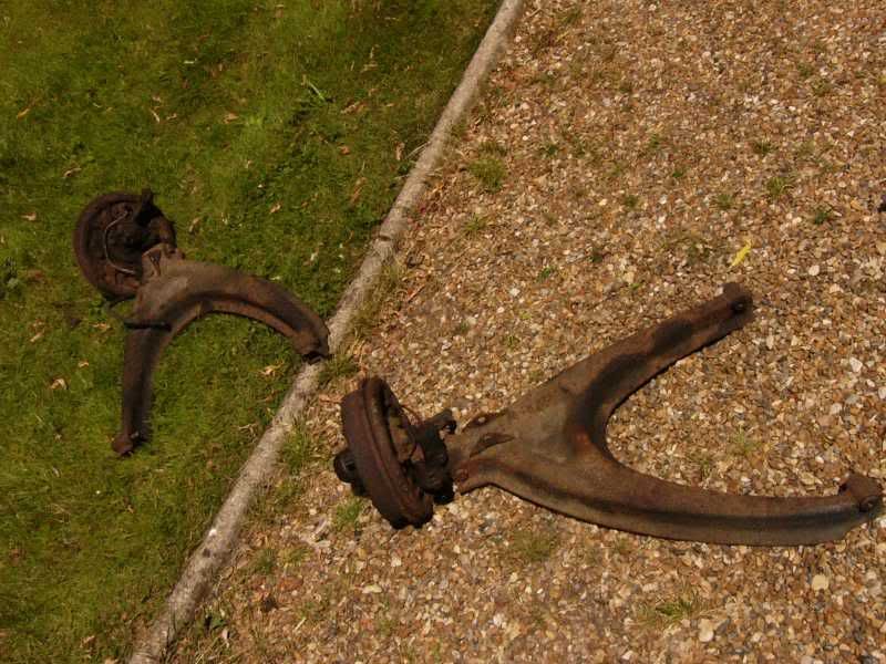
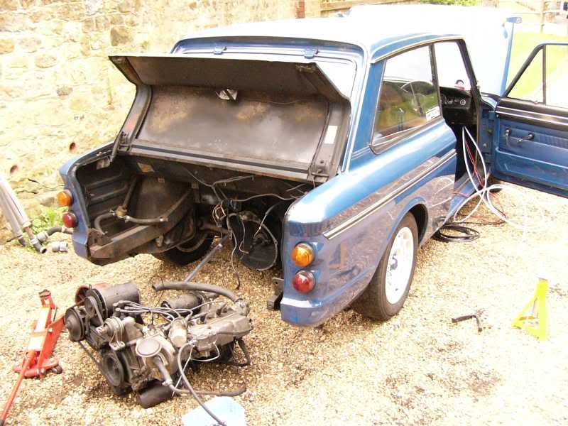
All the front end off -
Wishbones thrown as far as I could manage –
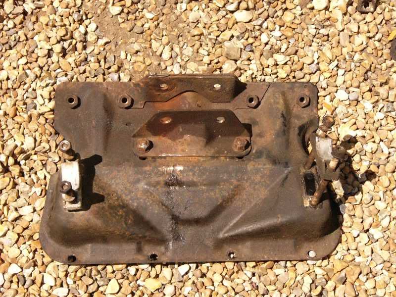
Rear suspension mount –
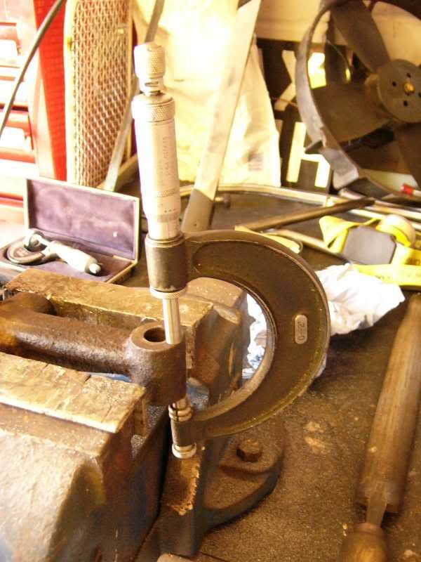
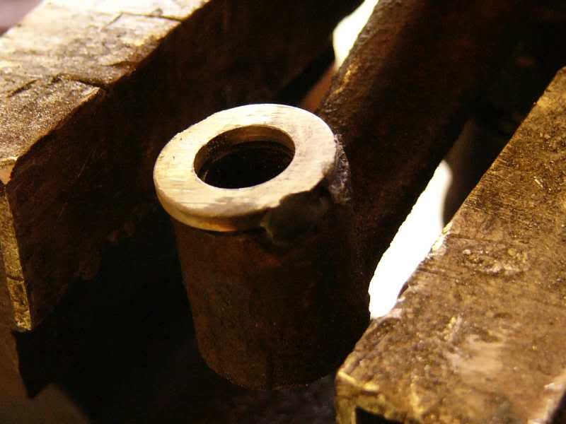
Once that was all off I had to rebuild the front hubs, pack them with grease, and then torque the bearings in correctly. As the car is pretty low now the front negative camber is unacceptable (I never thought I would say that!), to fix this I modified the kingpin carriers where they mount to the wishbones. 1/8th of an inch was removed from the top surface and then an 18th washer tacked on to the bottom, this removed about 3 degrees of the negative.
Hub rebuilt –
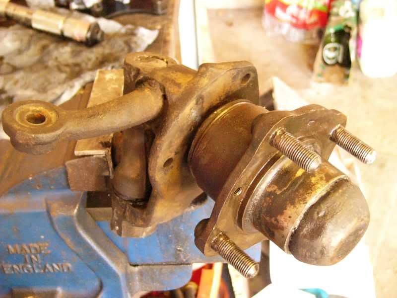
Measuring the mounting thickness, so I could take the right amount off -
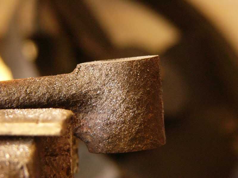
Before filing down –
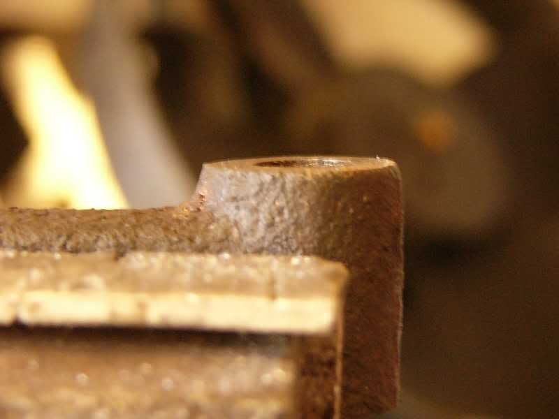
After filing –
Washer tacked on to bottom surface –
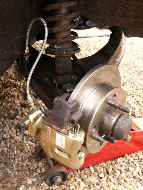
Next on my list was to build up my new disk kit, this is the fiesta conversion from Colin Valentine, I was really impressed with the quality of the kit and all the components. I also obtained reconditioned callipers, as this is a safety critical part I didn’t want to cut corners!
Disk kit –
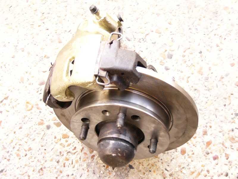
Disk kit -
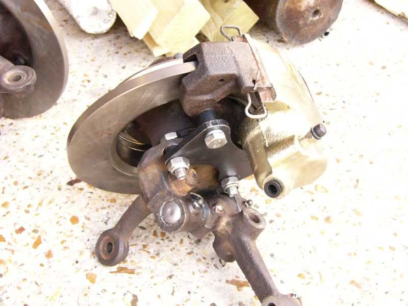
Then all of the new components were ready to go back on –
The new kingpins with added positive camber!
New disks in and ready, ooohhhh yeah, hopefully better than drums
And the camber before and after the kingpin modification –
That’s it for today, tomorrow my manifold is arriving hopefully (the guy posting it is being a bit of a retard :( ) So that will be modified to fit up to the imp manifold ready for welding. If I can get hold of an M5 tap set then I can fit the blower pulley on to the blower, and fabricate the mounts for it, if not then I can still make up all the flanges ready for the tubes to be welded on. I am going to have another go at the front rad conversion too I think, get it all fitted up and see how it goes. I can also run the fuel and boost lines front to rear ready for the injection.
Only 6 days to go, oh my will it be driveable?
More tomorrow guys and gals
J
Day 16 / 17 / 18
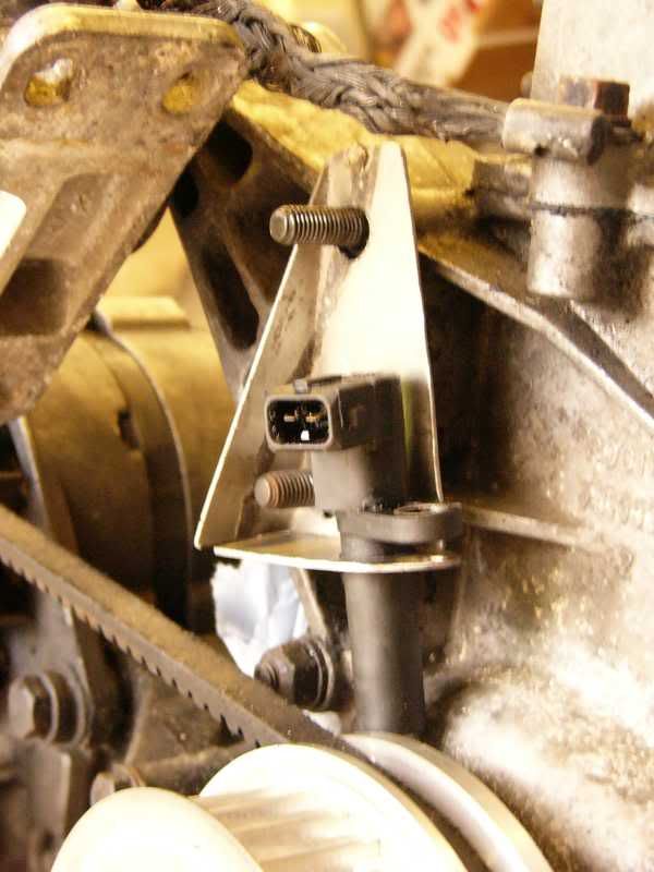
Well I’ve got a bit done over the past few days, all of the sensors for the ECU are in and ready to be connected up, the blower has its pulley bolted on (albeit with only 2 of the 6 bolts!) and the loom I received with the ECU has been paired back to the essential wires.
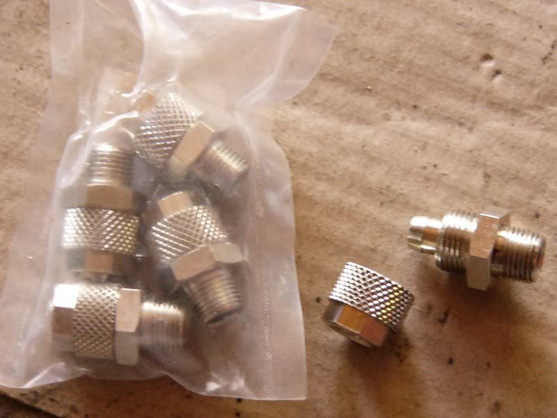
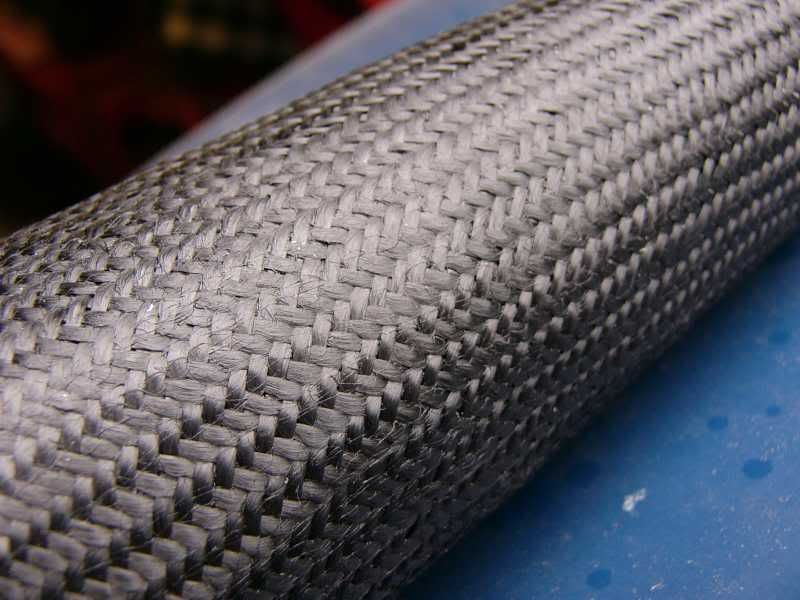
On Friday I stated by looking at the fluid transfer lines, I am trying to get rid of jubilee clips and joins, so all the fuel hose and boost lines are going to be this stuff –
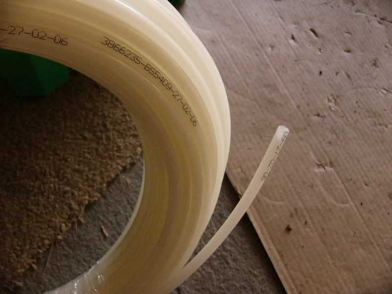
It is superflex nylon air hose, this is resistant to most fuels and oils and good for over 10bar pressure, should be fine with my Bosch pump then!
All of the fittings that the hose is joined with are nickel plated brass, they use no o-rings just the design to seal the hose.
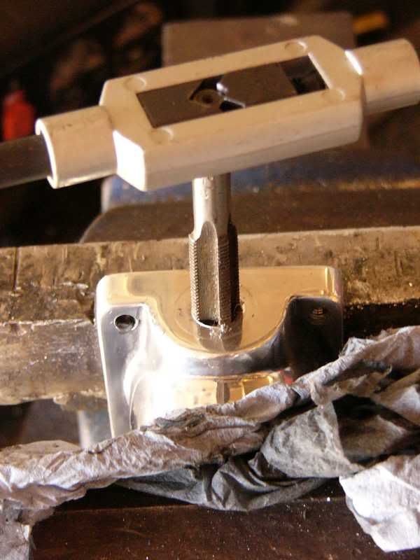
The fuel pressure regulator I purchased came with barbed fittings ready to receive rubber pipe and jubilee clips (god damn jubilee’s!), I removed all of the barbed fittings and tapped the holes to 1/8th BSP to take the nylon pipe fittings,
Fitting for the fuel rail as stock –
Barbed fitting cut off, drilled, and tapped –
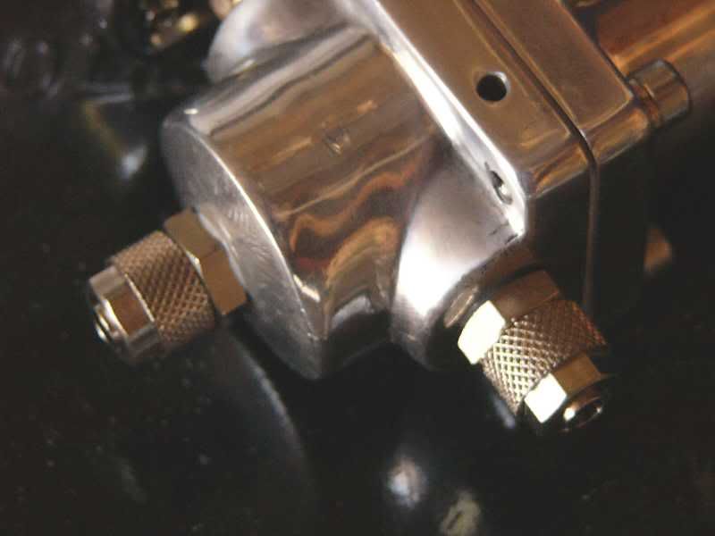
Nickel brass fitting in place of barbed fitting –
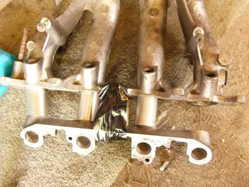
Then the manifold that I purchased from fleabay arrived, this was from a 1.4 K-series engine, it came with the injectors, throttle body, the whole sherbang! And all for 99p, booya
I jumped straight on it, cutting the imp manifold up to salvage the flange ready for welding –
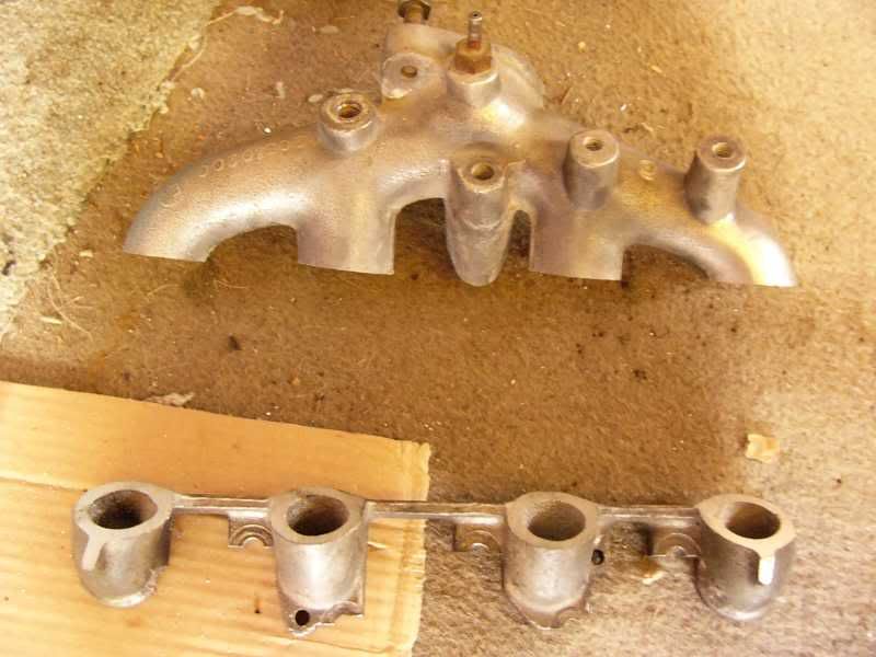
This was then offered up to the k-series manifold to start making the adaptor –
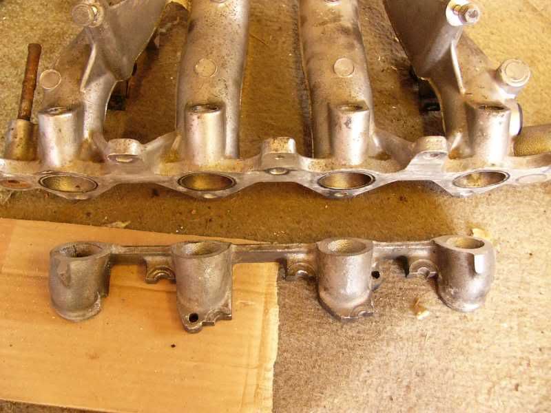
The two center ports are spot on and straight, but the two outside ones are about 30mm off, so angled adaptors will be made up. Here is a part way shot –
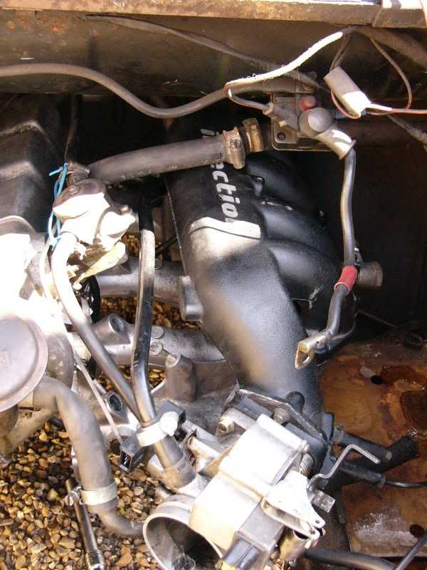
Eventually I am going to make up my own manifold in stainless steel, with a proper plenum chamber and trumpets etc.
To ensure I wasn’t barking up the wrong tree I offered it up to the engine that is currently in the imp, it fits like a glove with about and inch spare all round!
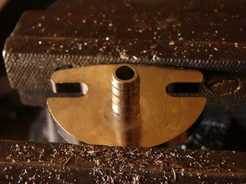
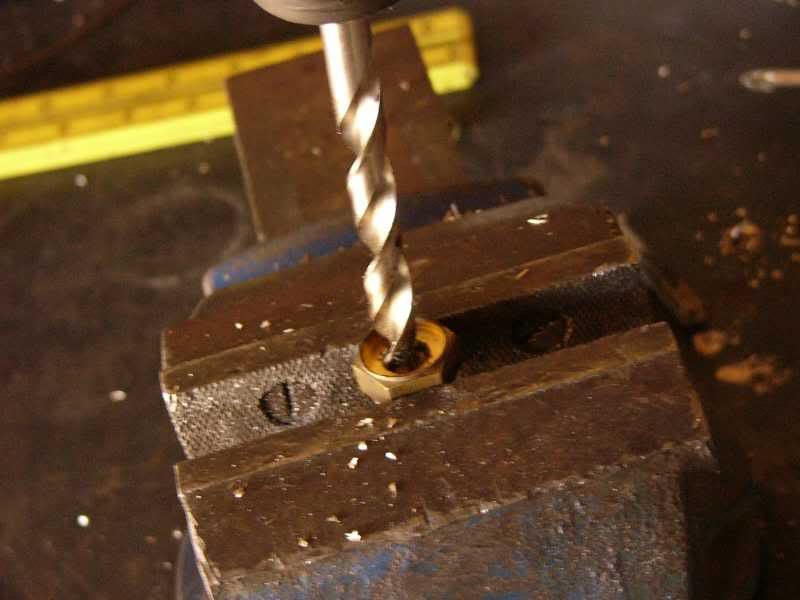
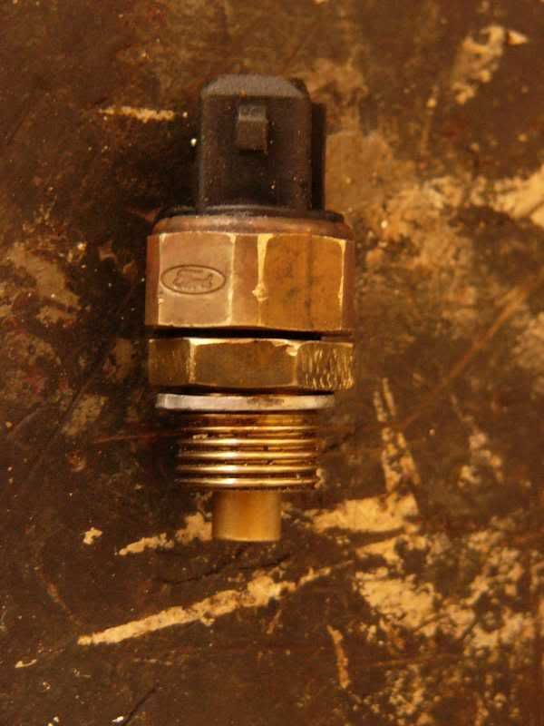
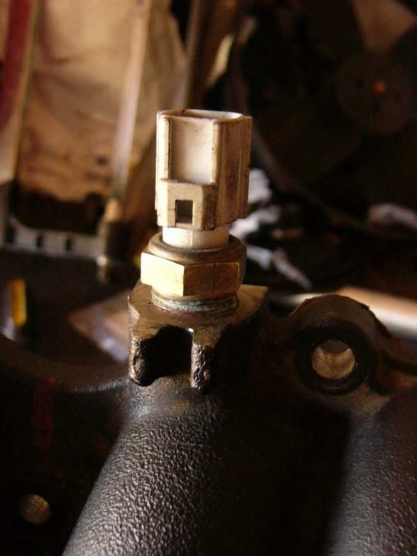
Next I decided to organize the water temperature sensor, to mate this to the imp head I used an old imp water temperature sensor, this was drilled out so that the centre of it could be tapped to take the ford sensor –
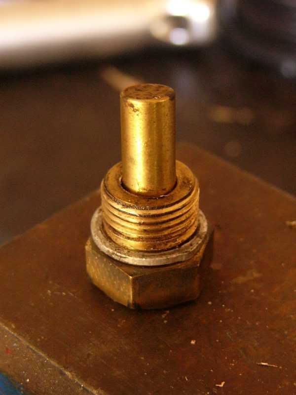
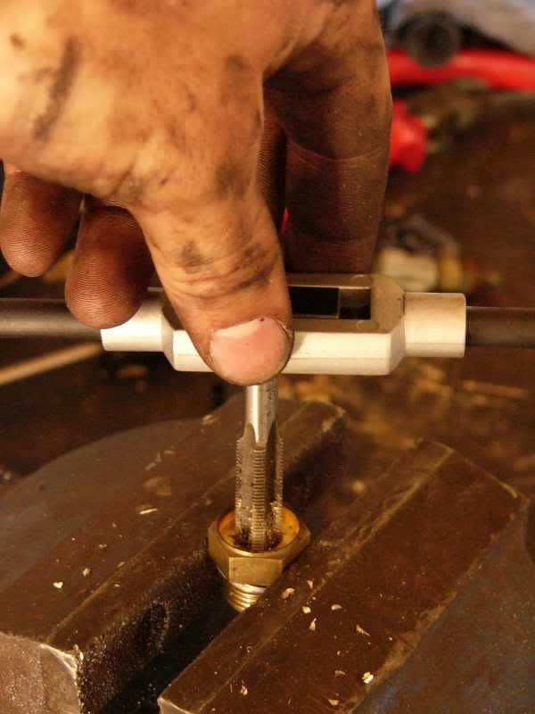
The finished adaptor and sensor looks like this –
Next on my list was the air temperature sensor, there was a fitting in the plenum of the k-series manifold, this was slightly smaller so I could just tap it out to the correct size for the sensor.
finally for the mechanical stuff I organized the mounting for the blower pulley onto the blower, I have used 12.9 cap head plain shank M5 bolts, these give a safety factor of around 6, should cover me I drilled the flange using the pulley as a guide, and then tapped the hole out ready to receive the bolts. Unfortunately I seem to only have two of these bolts, so tomorrow I will be getting four more for the other holes!
This afternoon was spent stripping the wiring loom down to the bare essentials, there was far too many wires and electrical tape, made the whole thing jolly messy! So I cut trimmed and peeled my way down to about ¼ of the original wiring, everything is much simpler now.
Tomorrow I am going to get some aluminium stock to finish the manifold adaptor, and the necessary bolts for the blower pulleys. I will also be putting my trigger wheel onto the crank pulley and mounting the VR sensor. I can fit the wide band O2 boss into the exhaust ready for the sensor, and finalise the wiring loom ready for braiding and heat shrink. Once the blower pulleys are mounted correctly I can finally get the blower mount together and order up the belt ready. Once the blower is on the tensioner can be fabricated.
More tomorrow
Cheers
J
On 5th of Sep, 2006 at 05:47pm mini13 said:
I reckon if his brains were gunpowder he couldn't blow his own hat off...
|
t3gav
2395 Posts
Member #: 229
Gavin@minispares.com
kent
|
|
Very impressed, where did you go to uni?
|
blown_imp
223 Posts
Member #: 598
Senior Member
Gaol
|
|
Swansea Institute of higer Education, it was fun and they taught me quite a bit! i just loved the beach there
J
On 5th of Sep, 2006 at 05:47pm mini13 said:
I reckon if his brains were gunpowder he couldn't blow his own hat off...
|
antman

966 Posts
Member #: 358
Post Whore
Snetterton, Norfolk
|
|
I was going to go to Swansea but ended up doing a HND in Motorsport at Brooklands College as it was closer to home and allowed me to work when not at College.
|
blown_imp
223 Posts
Member #: 598
Senior Member
Gaol
|
|
Day 19 – Oh iss ooown!
Well today was a full on 12 hour slog, I’ve been on the engine all day, but it was worth it, as the blower is mounted up!
I started out at 8am by going to a couple of places to pick up some nuts and bolts, all duly collected ready for various different areas of the engine.
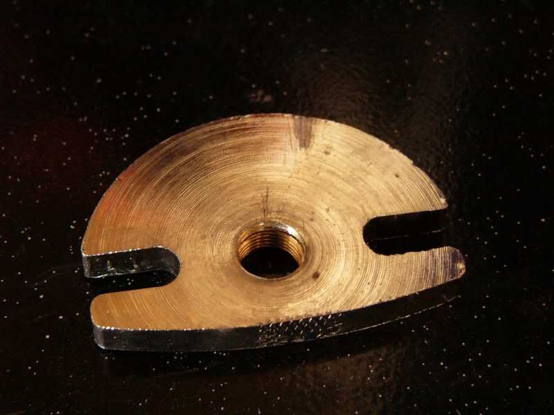
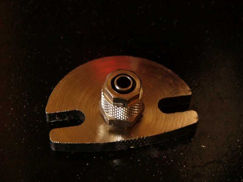
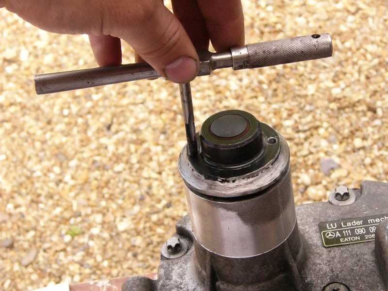
As soon as I got back I started getting the crank pulley mounted up, this involved pulling the pulley from Maynard’s apart.
The threaded holes were drilled out ready to receive the plain shank bolts, this pulley will be sandwiched (mmmmmm sandwich) between the blower pulley and the steel mounting boss. Once drilled the bolts were trimmed down to size, I then ran a die down them to clear the threads and put a drop of loctite on. This whole caboodle was then bolted on to the crank.
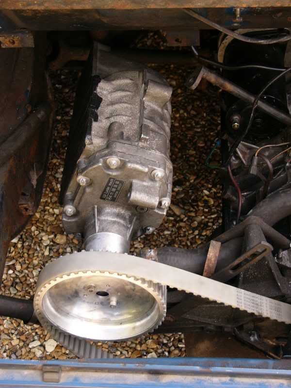
Pulley assembly on the crank –
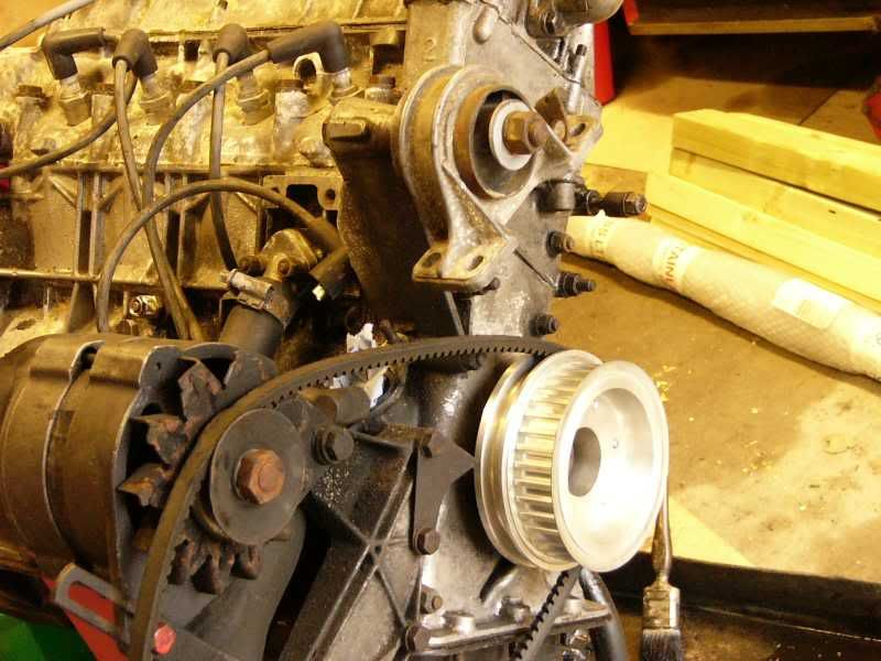
Once this was completed I could use the crank pulley to line up the blower, initially I made up a right angle bracket to support the nose of the blower, this bolted on to the water pump, and could be moved in the x and z plane.
I then cracked out a nice bit of kit, a laser level! With this I could line up the blower pulleys almost spot on, and the last bit would have to be done carefully by hand.
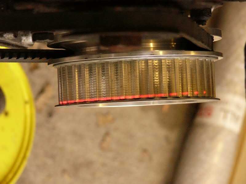
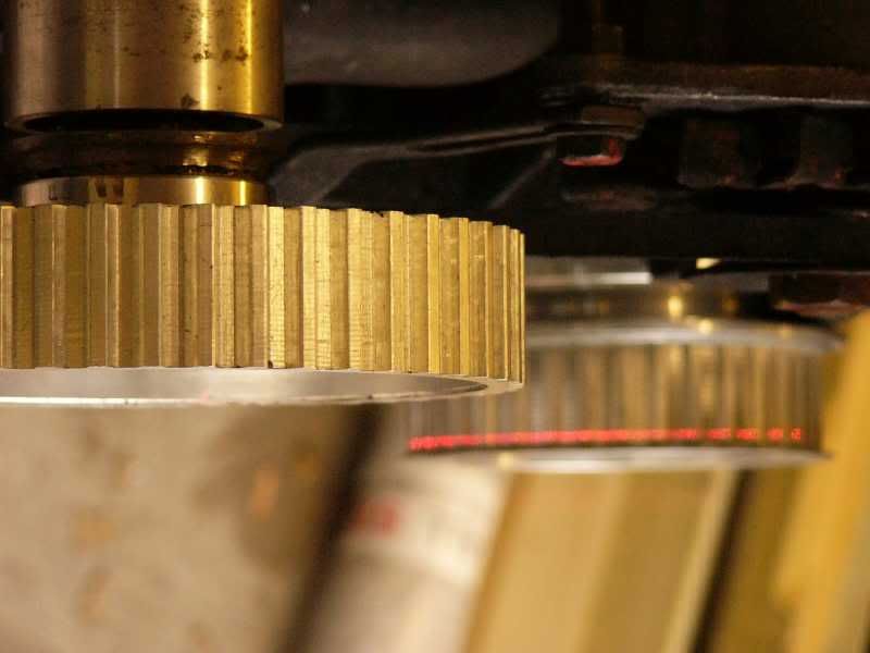
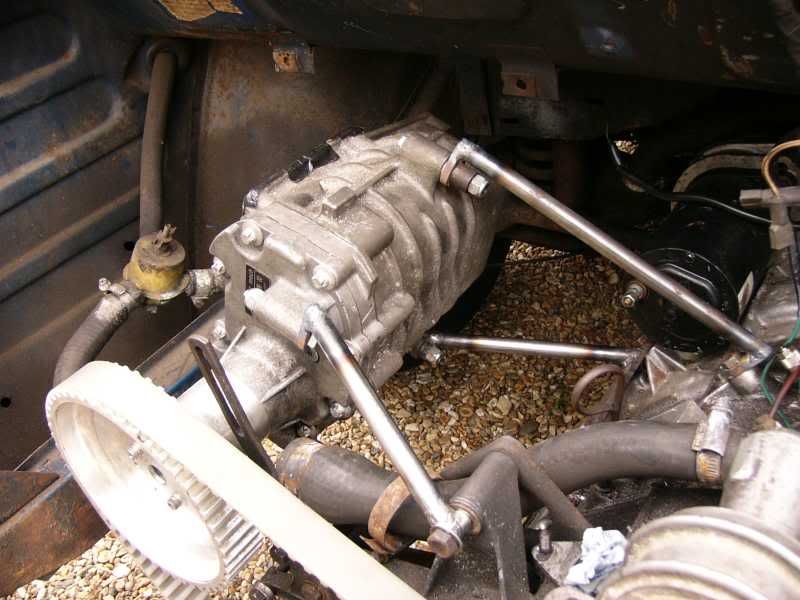
Once it was close I tightened up the bracket on the nose and started to make up the other supports that became the blower spaceframe.
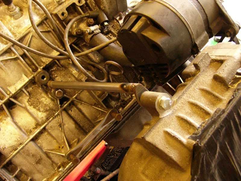
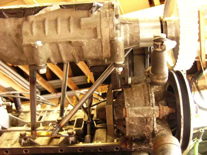
The first blower mount –
I carried on and made up all three other mounts and got the mounted up, the blower can have its position fine tuned using washers between the mounts and the blower itself.
I decided to knock up the crank trigger mount next, I decided to make this from my parents stainless kick board from the kitchen, I don’t think they wanted it anymore, did they? Anyways I cut out a template from card and then marked it up on the stainless.
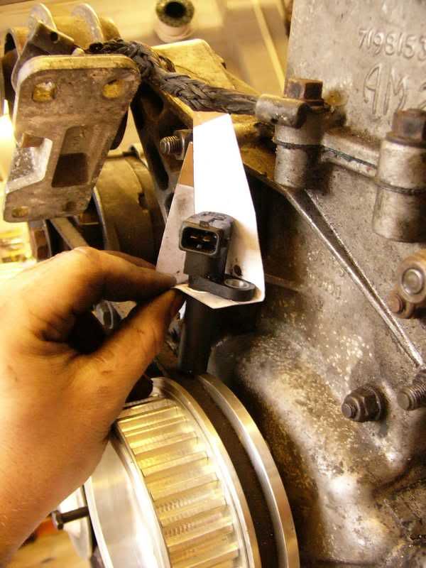
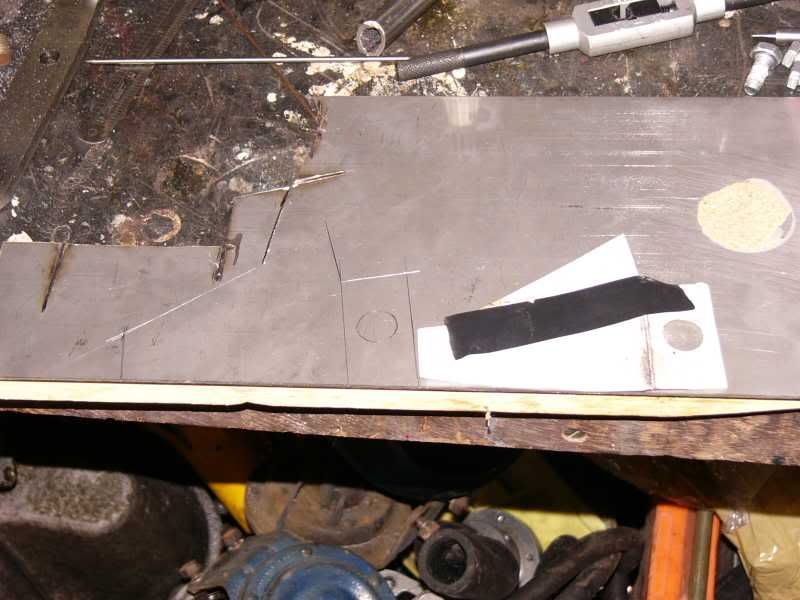
This was then drilled and cut to shape
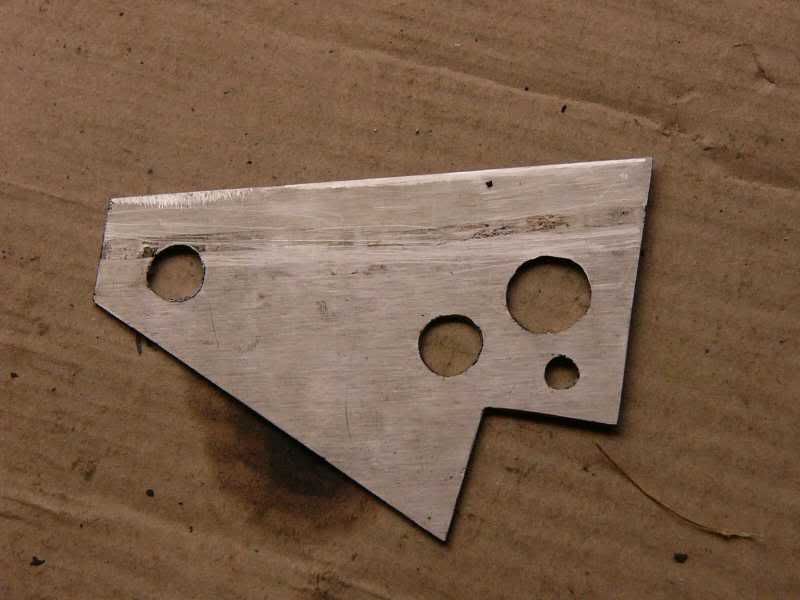
At this point it should be bent to resemble the card template, what I did was fold it the wrong way, swear a bit, and then start from scratch, its much easier second time round! After re scribing, drilling, cutting and folding this was the result –
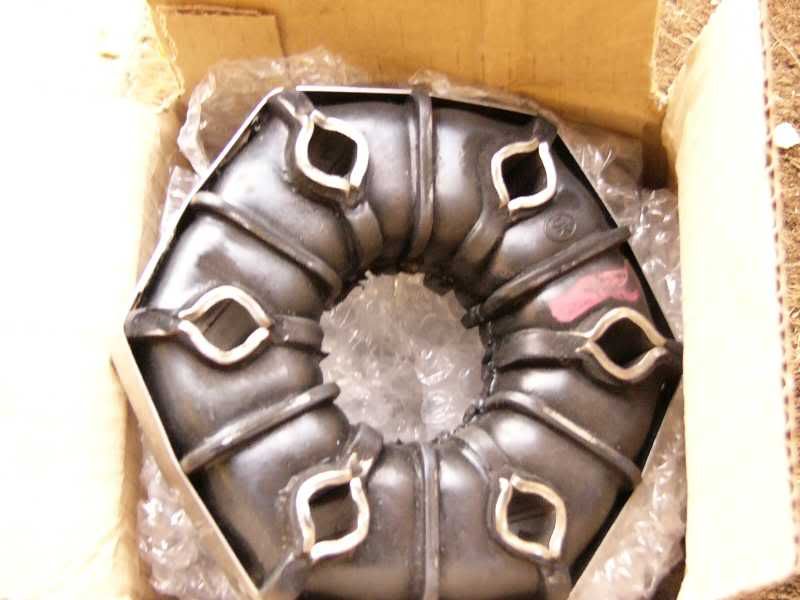
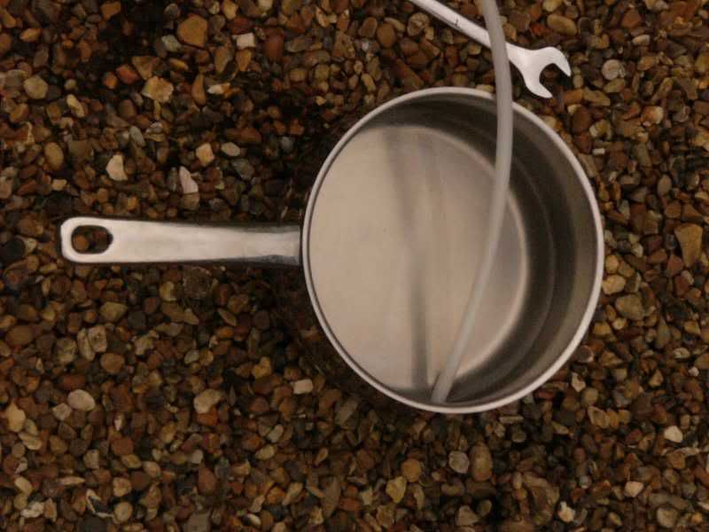
I also received some new donuts through the post today, nice lotus ones mmmmm. My car appears to be fitted with the SUK ones that are only meant as emergency spares! Will all be fixed soon
Tomorrow I shall be finishing the blower mount and crank trigger mount. I will re shim the tappets and re torque the head bolts, and then the engine can go into the car! Whoop whoop!
Cheers guys and gals
Day 20 – busy indeed!
Well today was jolly productive, so much so that I only had time for a few photos!
I began the day by making up all the conversion tubes for the inlet manifold, this was using the 7075 T6 tube gained on yesterdays parts mission. I have shortened them by 20mm to gain a little more clearance on the chassis rails.
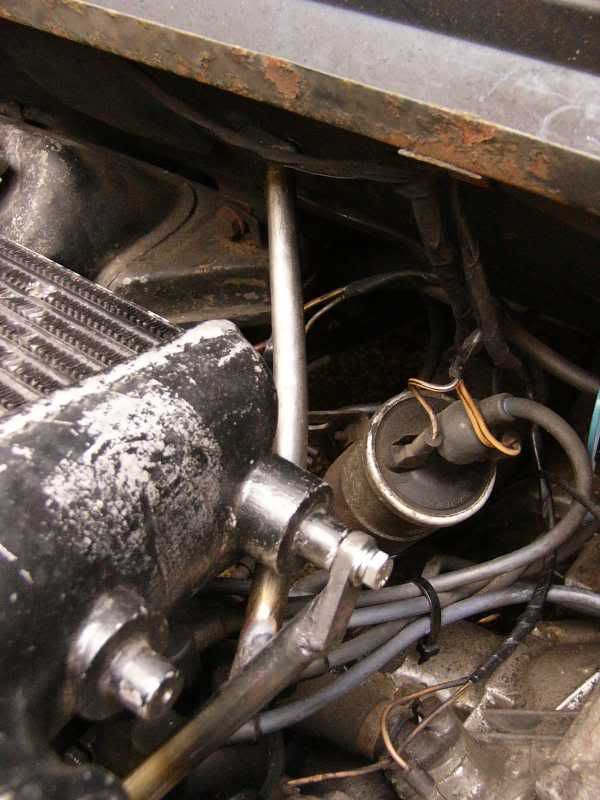
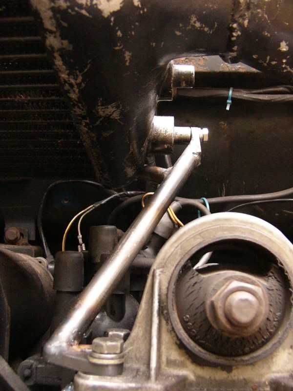
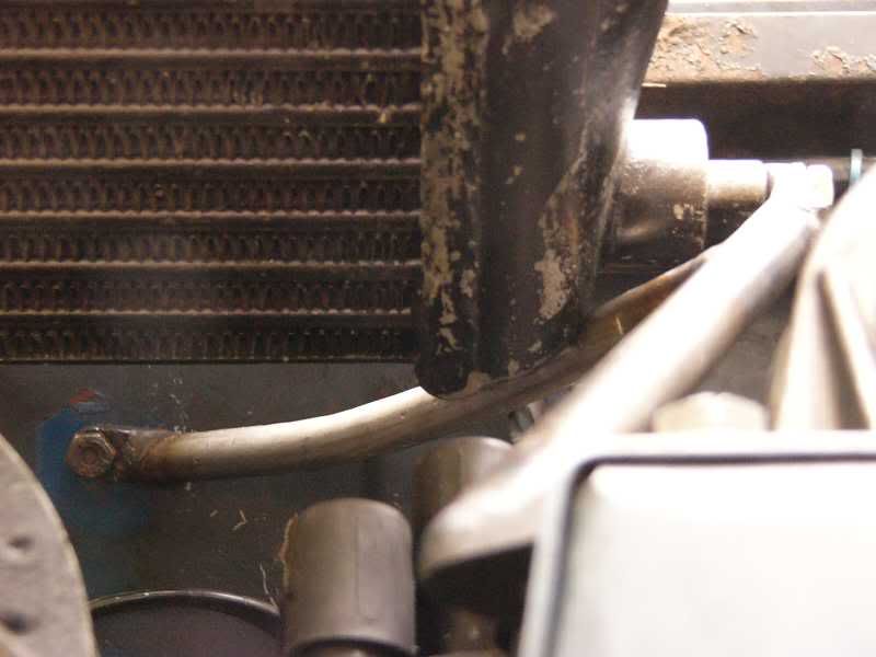
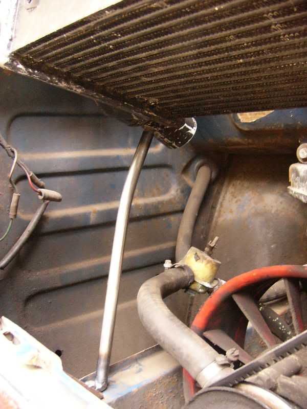
Next up I sorted out the header tank and radiator lines these are ‘temporary’ but will do to get me up to brands and then the ‘pod!
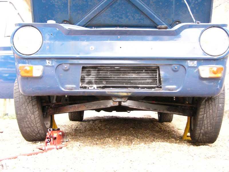
As everything is relying on something now, I next had to bleed the brakes, as once this was done I could put the fuel tank back in which would then let me fit the fuel pump and so the fuel lines!
I managed to get almost the whole family in on bleeding the brakes, I had my dad pumping the pedal, mum was topping up the reservoir, and I was on the calipers! The brakes bled very easily, and I had a god pedal within 1/2hr. I think I may go up to a 0.75” master cylinder though, as the pedal is still a little soft for my liking.
Car up in the air for brake bleeding –
Once the brakes were bled I could fit the fuel tank back in, to get my fuel line to connect to the tank I had to use one of my wizzo nickel brass fittings, fortunately Rootes has kindly put the correct thread into the tank ready for me!
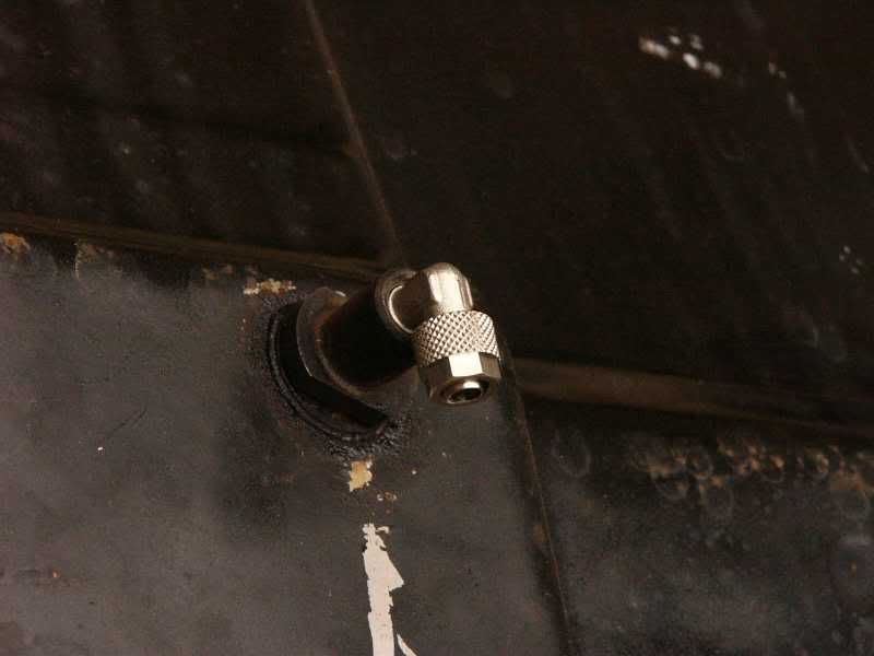
This then fitted perfectly back into its corresponding hole and the line could be fitted up to the fuel pump, again into a nickel brass fitting. The tube is quite stiff and so I jolly difficult to get onto the nipple of the fitting, this is easily solved using boiling water to soften the pipe –
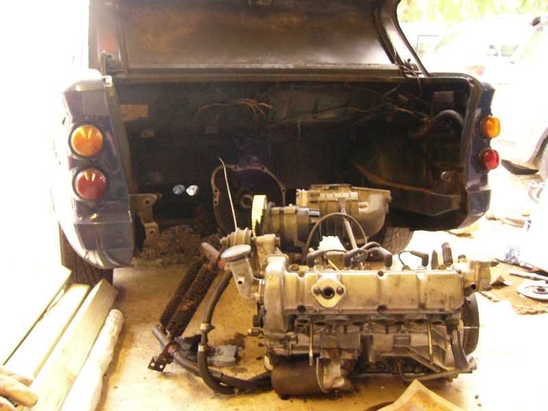
At this point it was time for lunch, this was over shortly and I cracked on with the afternoon’s jobs. Top of the list was taking the old engine out, this was a simple job taking all of 1/2hr, was mega dirty though, ended up with black hands :(
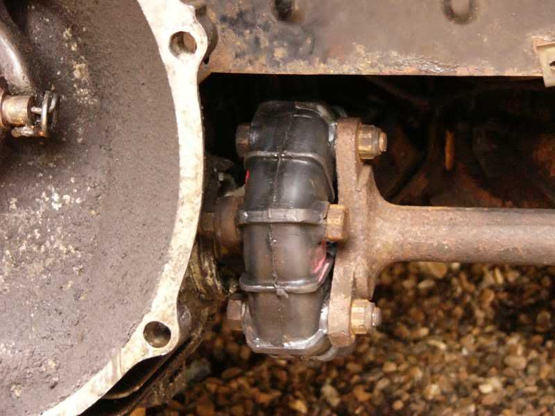
Once this was out I could replace the faulty original donuts, these were a little worse for wear being perished and a little torn around the metal tubes. If the car was to be stock they would be fine, but as it should have around twice the standard power I thought better of keeping them!
Anyone who has fitted imp donuts will know how much of a PITA they are, so this took a good couple of hours and a bit of swearing, all ended up fine though, nice and shiny!

Tomorrow morning I will be getting up to put the engine in at 7.30am, this is so I can have the assistance of my dad, its not really a one man job! Once this is in I can think about doing the boost pipes in stainless. The engine management system can be plumbed in and I can also wire in the battery again. I will finalise the rad tubes, and the blower belt will arrive so I can ensure the blower is straight.
So much to do and only 3 days left, holy moly indeed!
More tomorrow
J
p.s. sorry if there arnt as many funny bits In these updates as in the beginning, this work schedule is wearing a little thin now!
On 5th of Sep, 2006 at 05:47pm mini13 said:
I reckon if his brains were gunpowder he couldn't blow his own hat off...
|
blown_imp
223 Posts
Member #: 598
Senior Member
Gaol
|
|
Day 21 – will it, wont it?
Hi guys
Well today has been full of ups and downs, I got up at 5.30am and ive now been working for 9hrs straight, im tired and its not going my way.
I started out with removing the engine from its stand and then fitting the clutch
Then the engine was lined up and prepared to fit into the engine bay
It slotted in very easily, and was bolted up before breakfast, in fact it was in by 7am!
Once it was in I sorted out the crank trigger and pressed the trigger wheel on to the pulley, this was arrange to be the specified 90 degrees before the trigger when at TDC.
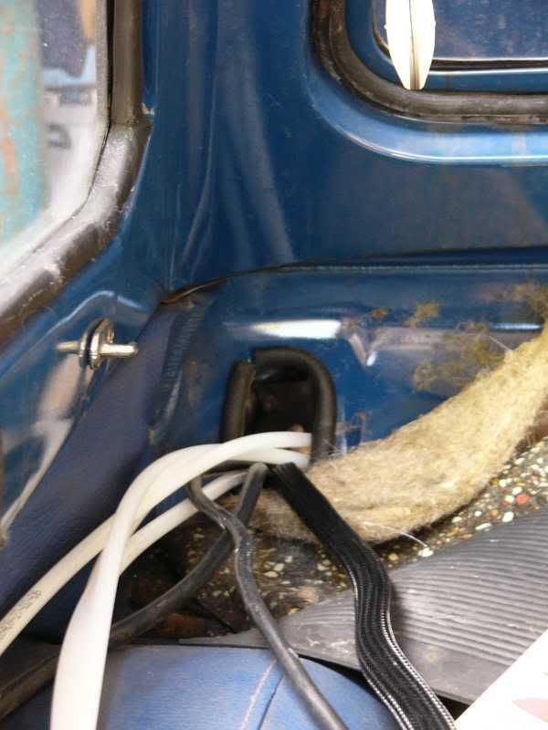
Next I ran the fuel lines through the car, including the oil pressure line and the boost reference line. To get them through the rear bulkhead I had to make a hole big enough to take the DB37 connector, to achieve this I used my hole saw again. Once drilled I lined it with split hose to protect the lines going through.
Over lunch I made up the DB37 cable that runs between my ECU and my relay board, this has about 30 wires that all individually connect to the DB37 terminations. It can be seen in this picture –

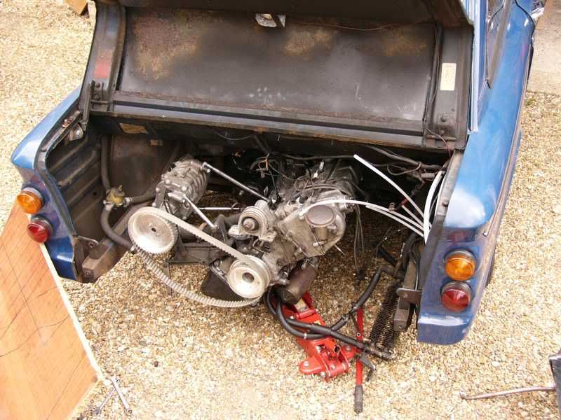
At this point I put the intercooler and rear cross member into position, and ‘the’ problem arose. The blower fits in, but there is not enough room above it for the flange or fittings to and from. What to do?
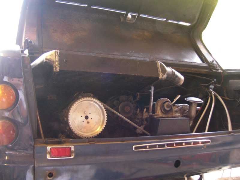
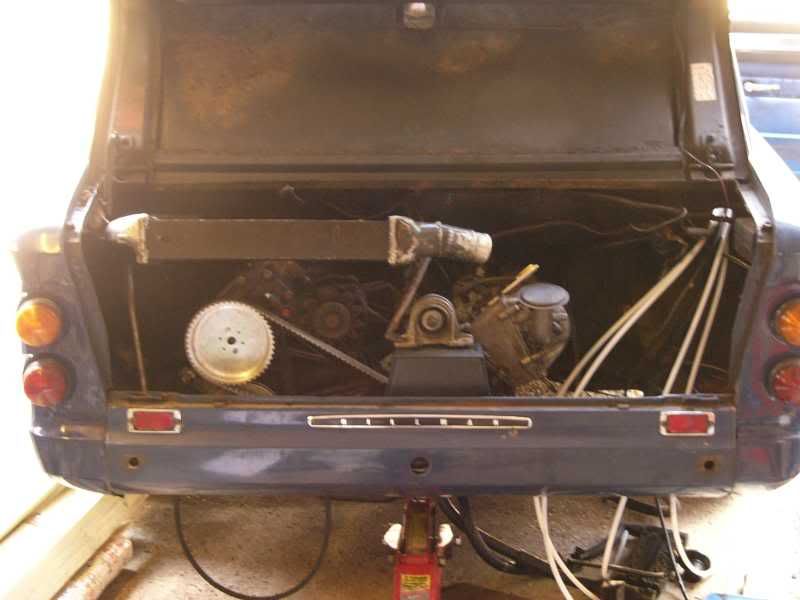
Here is the problem, the top of the blower is almost in contact with the rear shelf, do I cut it, or remake the blower mounts?

Cheers guys
J
Day 22 – Trying to not curb the enthusiasm!
Right well today I got bored of applying for jobs, and the sun was out, and I had a little itch inside. The kind of itch that is only scratched by a supercharged and injected imp!
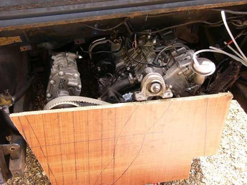
I haven’t had this itch for some time and I was starting to get worried, when it appeared today I didn’t want to extinguish the flames by going in too quickly, so only an hour has been spent. I’ve taken stock of the situation and started to look at the options, this is where we were left –
Here is the problem, the top of the blower is almost in contact with the rear shelf
So today I took all of the offending components that were causing obstruction, this way I can start with a fresh hole and the most important components, I.e. – Blower first
Bits out –
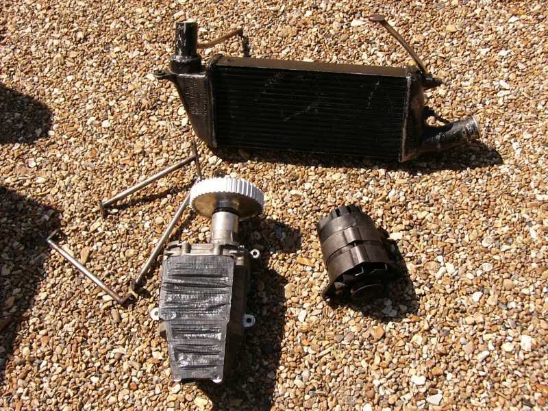
Hole left -
What im going to do is move the blower over to where the alternator was, then move the alternator to where the water pump was, and the water pump is going to be disposed of. An electric one will take its place.
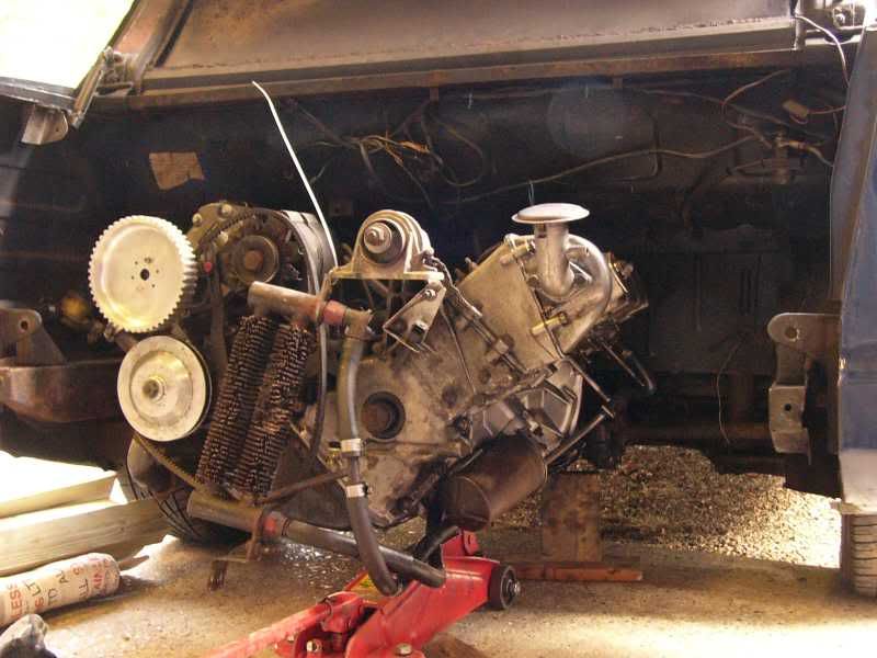
Blower sort of in position with flange and pipes –
(please excuse the photo, I was holding the blower with one hand and taking the picture with the other )
I think that the blower will be even further canted over so that the flange is almost vertical, this way i know there will be the room i need.
Tomorrow I will have a go at making up some new mountings, the advantage of this position is that I can make the mounting positions more solid, hopefully minimising flex and belts being thrown off. This position will also mean a shorter belt!
Hope everyone is well
Cheers
J
On 5th of Sep, 2006 at 05:47pm mini13 said:
I reckon if his brains were gunpowder he couldn't blow his own hat off...
|
AL

549 Posts
Member #: 1347
Post Whore
Croydon (South London)
|
|
Cracking little car mate  Think ive seen this on turbosport but my ford mates show me so much on there i lose track. Keep up the good work, makes interesting reading. AL Think ive seen this on turbosport but my ford mates show me so much on there i lose track. Keep up the good work, makes interesting reading. AL
|
blown_imp
223 Posts
Member #: 598
Senior Member
Gaol
|
|
Cheers Al, yeah ive been pimping it on a few forums especially since ive borked my leg and cant do much "real" work
Ill post some more i think!
J
On 5th of Sep, 2006 at 05:47pm mini13 said:
I reckon if his brains were gunpowder he couldn't blow his own hat off...
|
blown_imp
223 Posts
Member #: 598
Senior Member
Gaol
|
|
Day 23 – Getting back to where I finished!
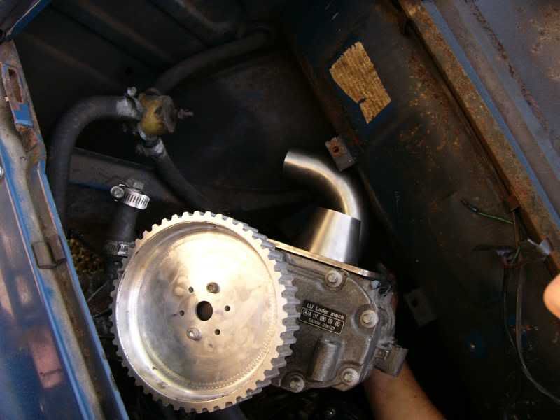
I got back from work at 3pm and jumped on the car again today, I started by totally removing the water pimp, this has left enough room for the supercharger to fit to the pumps mountings. This leaves the supercharger flange at almost vertical, it also means the alternator can stay in its current position. I bolted up the blower with one of the brackets that was left from the previous installation, this was tightened so I could align the pulleys.
Here I used hexalite Kevlar nomex board as a flat surface.
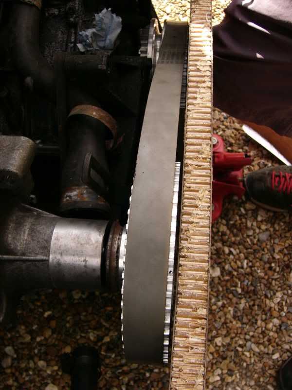
Once it was aligned
It can be seen how a small difference in position can make a massive difference in viability! One of the old mounts can be seen next to the blower, it’s not far out but enough to make all the difference.
Once it was in the right position, I started to make up new mounts. This was quite heart breaking as I had to hacksaw through my beautiful TIG welds :(
And then on to the new mounts
Work tomorrow, so some more soon, just not too sure when!
Cheers
J
Day 24 – OH IT’S BACK OOOOWWNNNNN!!!!211!12
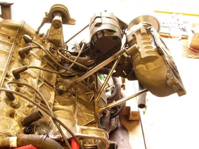
Progress today has been excellent, I’m back to where I was when I was involved in the mojo mugging. The blower is back to being solidly mounted, and it appears to be straighter than it was previously, also the mounts are stiffer due to them being shorter and triangulated.
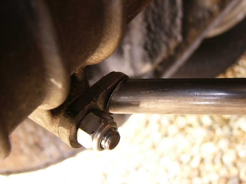
I started today with the front upper mount, I have decided to fix this one to where the alternator used to be. Unlike the rest, this one uses a small piece of tube instead of 5mm plate, this made it much easier as the bolt was in the wrong plane.
The mount at the blower is one of the recycled ones from the previous mounting, I cut a length of tube and shaped the ends to fit snugly in the gap.
Once it fitted well, it was tacked and then fully welded
Next I started with the lower rear mount, this was the same process –
Tube cut to length –
Ends marked with a scribe to indicate the angle –
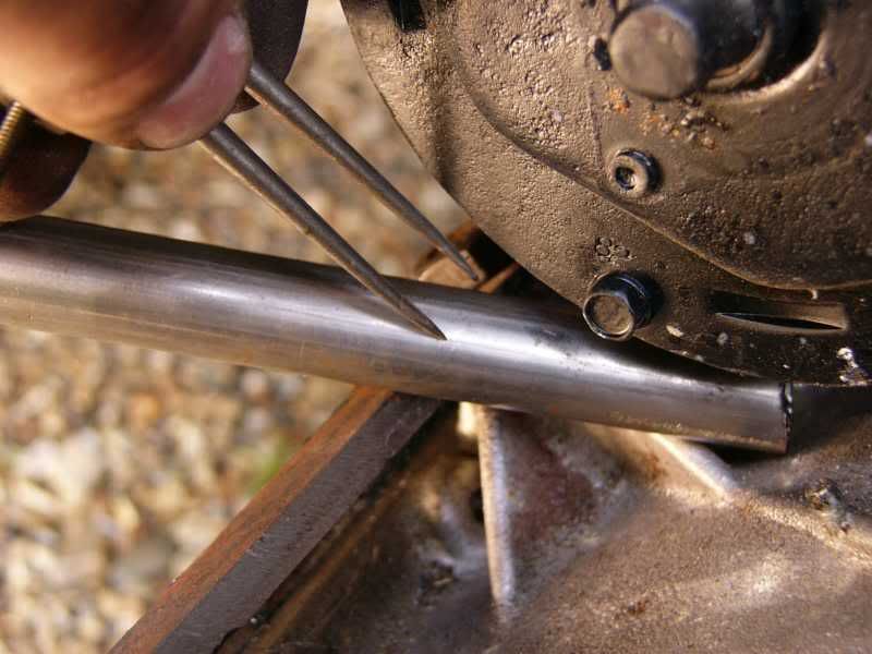
Then filed carefully to fit the gap, this is done slowly with lots of trial fits, essential for no gaps! In this picture I need to remove material from the lower side toward the back.
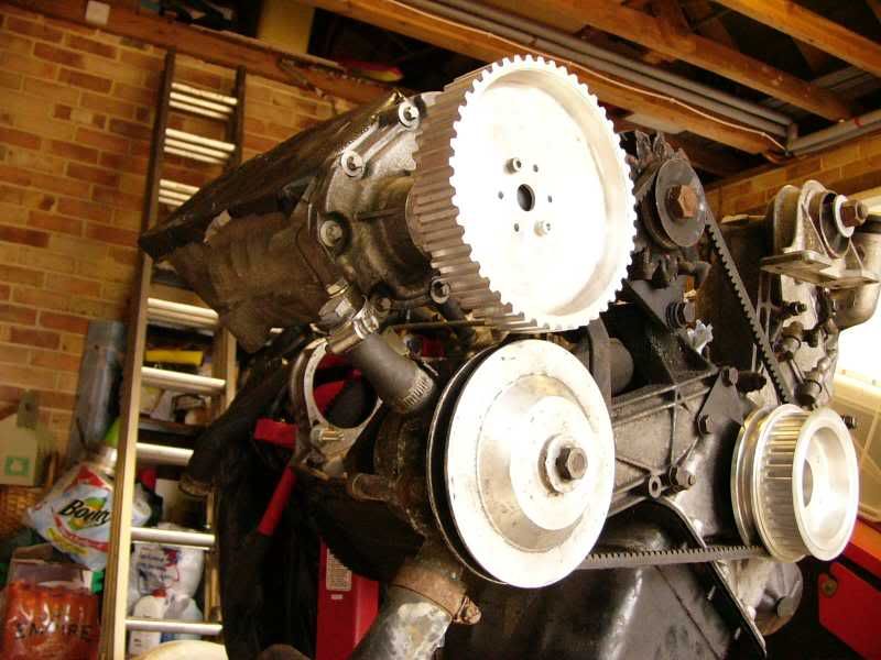
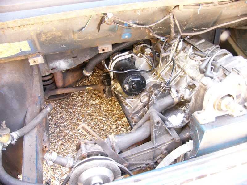
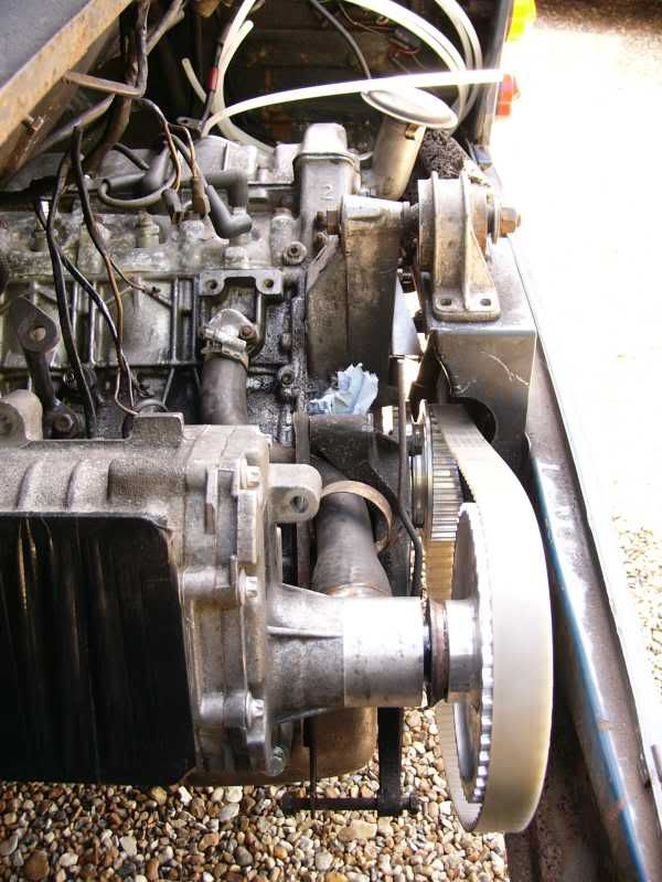
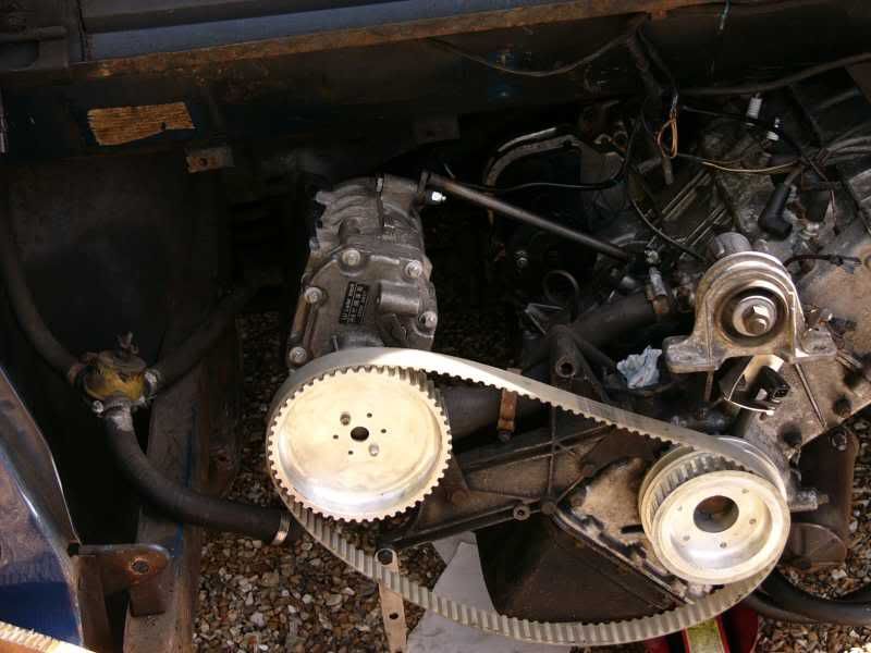
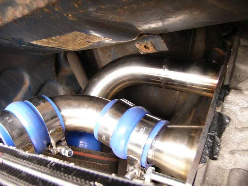
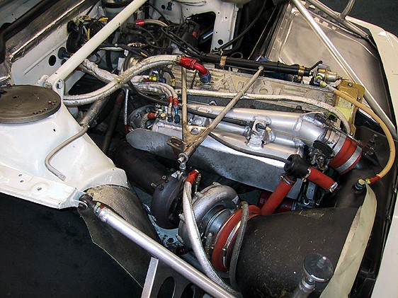
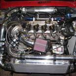
The lower rear mount was also completed and this is how the blower turned out –
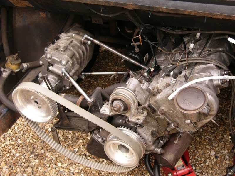
one more of the whole engine bay –
Tomorrow I shall get on with some more bits, new things! I’m going to take another look at the inlet manifold but that really has me stumped at the moment, I’ve got to get the imp flange joined onto a manifold with injector bosses, a plenum and throttle body. Not easy!
I’m also going to start wiring up the sensors and relay box, yay for injection!
TTFN
J
Day 25 – MMmmm Lovely TIG welds
Hello again, it’s sunny here but quite windy, windy enough to blow out my TIG arc!
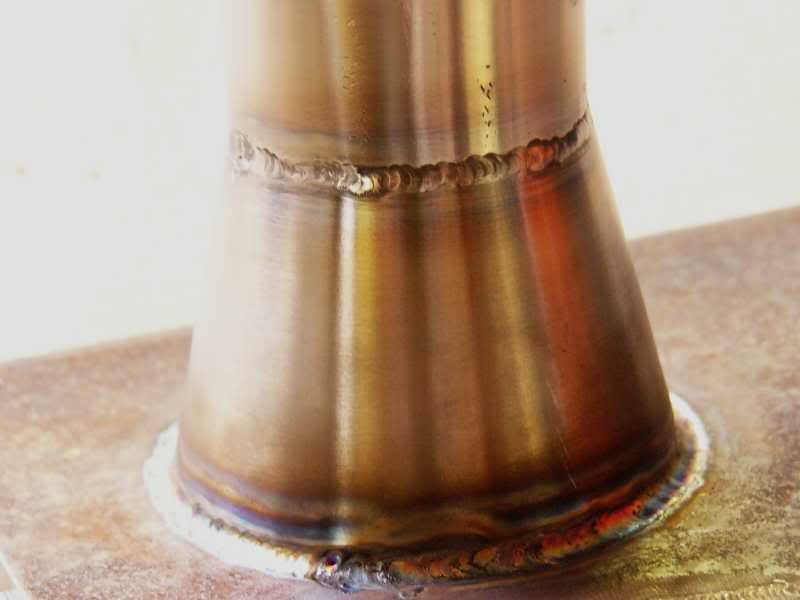
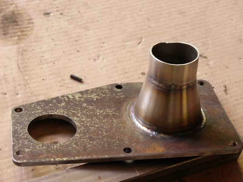
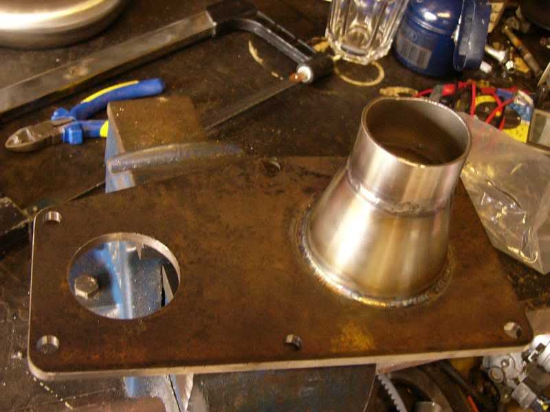
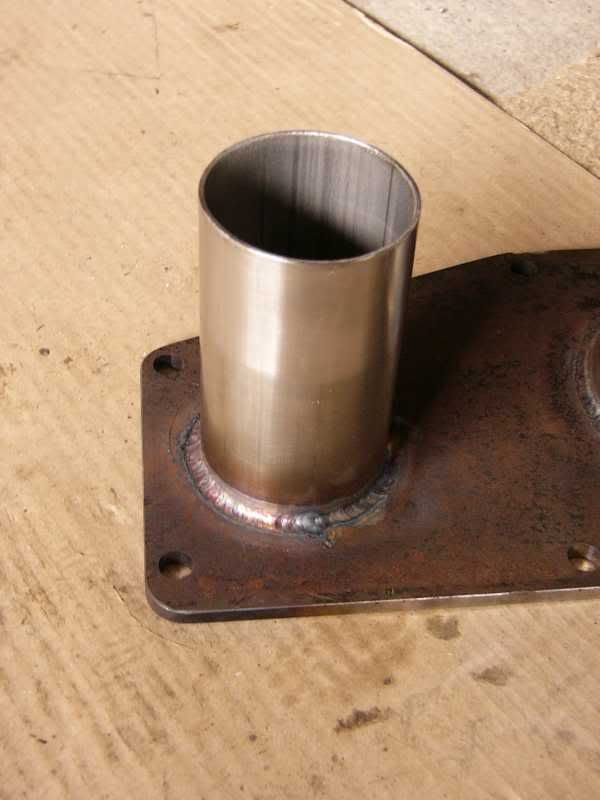
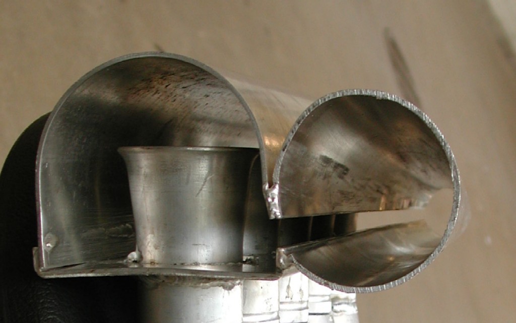
Today I started by looking at the blower flange, the outlet has a 3” to 2” reducer that needed welding in. This is how it started with the CNC’d 5mm steel flange and 316 stainless fittings –
My welding has been improving over the course of this project, I think I peaked today, just beautiful!
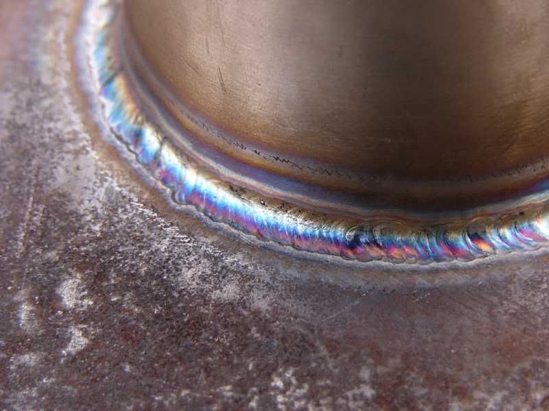
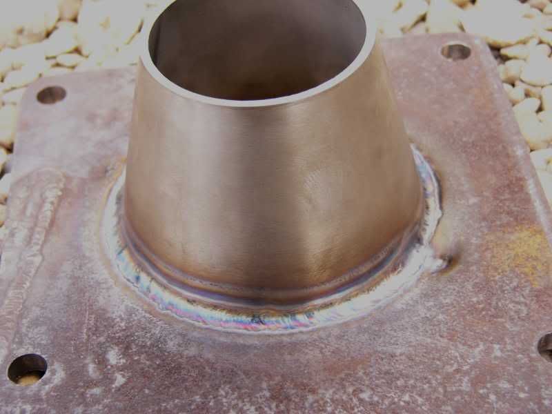
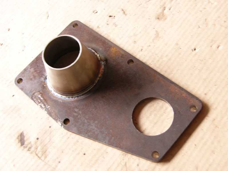
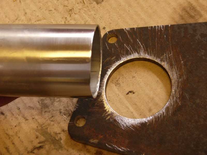
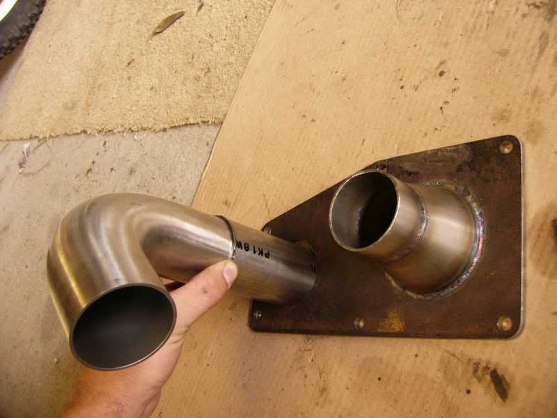
To this reducer I have to have a straight section to attach my silicone hump joiners, this is only about 1” long but just enough, space is jolly tight. I clamped the two parts in the vice and tacked them together, then I checked it on the car for fit.
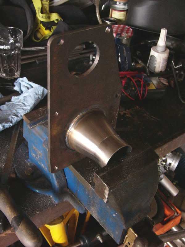
Once I knew it was a good fit I welded them together fully
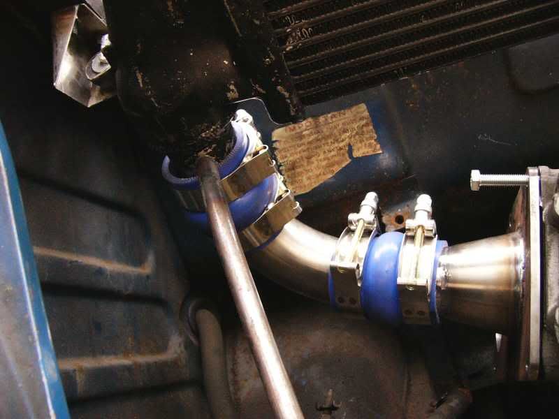
I had to shorten the inlet to the intercooler once again and also shorten one side of the mandrel bent 90 degree pipe as well, this improved the fit substantially. I also adjusted the angle of the intercooler down as much as I could before it obstructed the bonnet closing, again to improve fit.
Here is the finished article mocked up in the car, none of it is tight yet as I have yet to fit the inlet pipe to the supercharger.
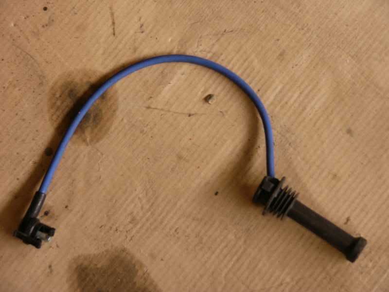
I decided to look at the electrics today as well, one thing that was bothering me was the spark plug leads, the original imp ones don’t fit the coil, and the ford EDIS ones don’t fit beneath the rear shelf in the imp engine bay. I was going to buy some custom made Magnecor leads, but these are £80, and I don’t have £80! I had a look at the EDIS leads and realised that the protective boot at the plug end was slipped over the lead, and could be cut back. I didn’t have anything to lose, so I had a go!
The original lead –
Knife and rubber shrapnel! -
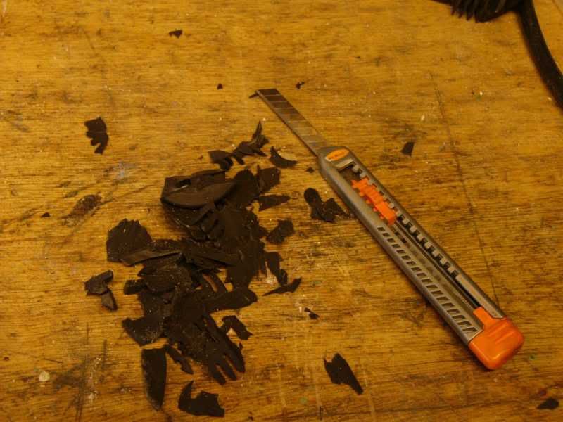
I sliced almost all the way though with the craft knife –
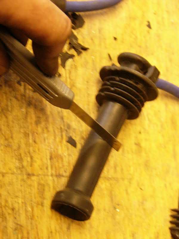
And the stretched the rubber until it tore through to the lead underneath –
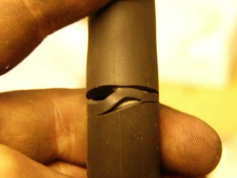
This is before and after removing the protective boot –
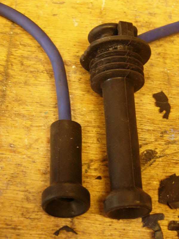
And the shortened lead –
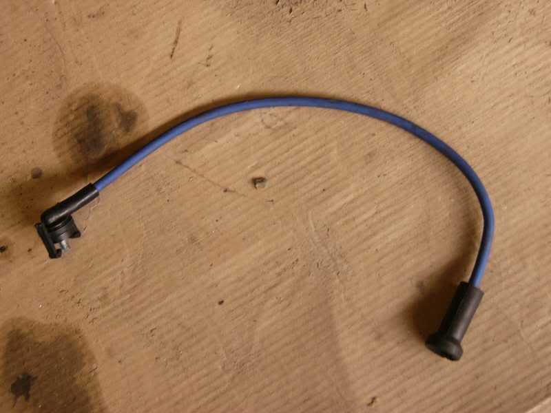
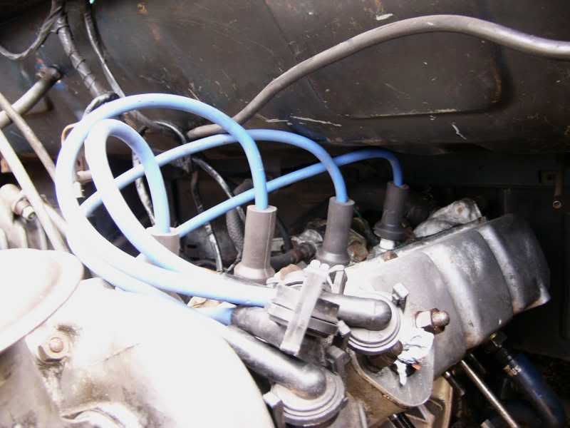
This is the leads fitted onto the imp engine –
That’s all for today guys, tomorrow I am going to finish the inlet side of the blower ready to take an air filter. I will also take another look at the electrics, fit the coil, relay board, and EDIS kit.
Thanks
Tatty byes
J
On 5th of Sep, 2006 at 05:47pm mini13 said:
I reckon if his brains were gunpowder he couldn't blow his own hat off...
|
Joe C
12307 Posts
Member #: 565
Carlos Fandango
Burnham-on-Crouch, Essex
|
|
Good tip on the ht leads, i have the same ones and they're going to foul the plenum, hadn't given it any thoght yet but that'll do the trick!
must say I miss the quickness of changing an imp engine!!
piece of piss compared to a mini
On 28th Aug, 2011 Kean said:
At the risk of being sigged...
Joe, do you have a photo of your tool?
http://www.turbominis.co.uk/forums/index.p...9064&lastpost=1
https://joe1977.imgbb.com/
|
blown_imp
223 Posts
Member #: 598
Senior Member
Gaol
|
|
Yeah the imp engine change does resemble a slice of victoria sponge, super easy!
As for the leads, i really couldent stomach £80 for a set of leads that were no better than the stock parts. Just watch out for the inner, take it real easy with the knife as any nicks will probably cause problems!
Cheers
J
On 5th of Sep, 2006 at 05:47pm mini13 said:
I reckon if his brains were gunpowder he couldn't blow his own hat off...
|
slater

1030 Posts
Member #: 1291
Post Whore
Suffolk / Birmingham
|
|
good stuff J, im proud to have part of my calipers going on such a cool motor! 
|
blown_imp
223 Posts
Member #: 598
Senior Member
Gaol
|
|
Hi slater,
Yeah cheers for that mate, i really appreciate those callipers!
Just slowing getting up to speed on here so i can post some new updates.
J
On 5th of Sep, 2006 at 05:47pm mini13 said:
I reckon if his brains were gunpowder he couldn't blow his own hat off...
|
blown_imp
223 Posts
Member #: 598
Senior Member
Gaol
|
|
Day 26 – blower side done
Just a quick one
Started here –
I cleaned up the surfaces between the straight section and the flange ready for welding –
And proceeded to weld it up –
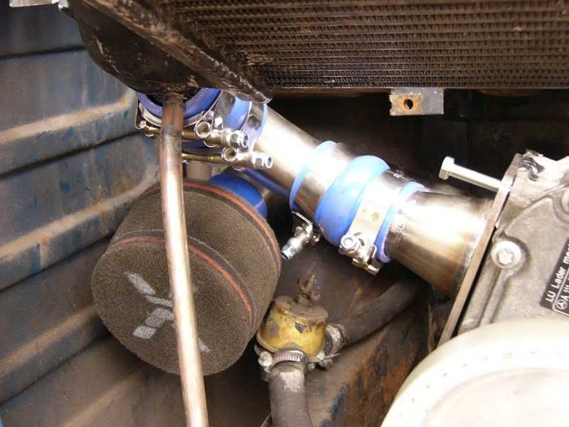
This was the lined up with a 90 degree mandrel bend to fit a filter to and welded up –
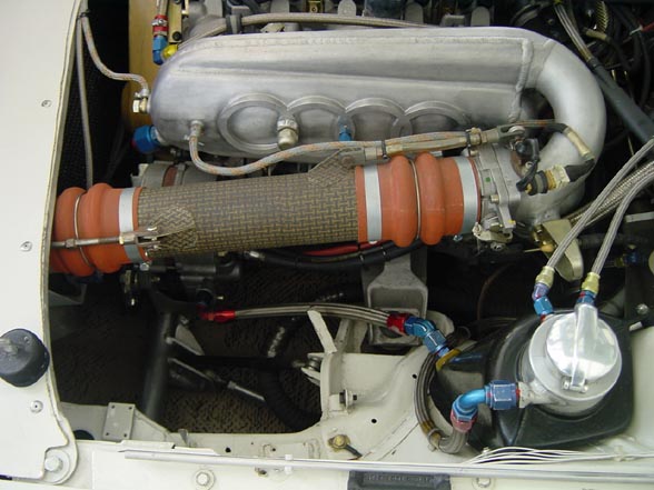
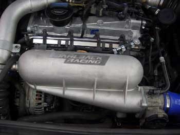
Here it is in the car, mmmm shiny lovelynes
Had a look at the wiring too, shouldn’t be too difficult, I also bought a set of 32mm CBR600 throttle bodies, got to make up a plenum chamber as well now!
J
Well time for a proper update
I’ve been driving myself crazy over the car, as I haven’t been able to complete as much work as I would have liked. Fortunately I have things back underway, I’ve decided to get the manifold made up by the Bogg brothers so I have had time to concentrate on the rest of the inlet system.
I have been trained in a program called I-deas, which is a 3D drawing program designed and created by the devil himself. Its is incredibly un-intuitive, and very very very very complicated, it taken me four years to get anywhere near being able to use it! Despite being jolly hard to use and quite demonic, it is a very powerful program and means I can create some nice drawings, these can also be FEA’d in the same program or exported to Fluent for computational fluid dynamics.
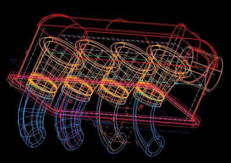
So to decide how to do things I drew most of it in I-deas –
Here is a wire frame model of the entire setup minus the throttle bodies them selves.
This is a solid model viewed from under the plenum without the back plate.

And the trumpets showing the slight kink to fit inside the plenum.
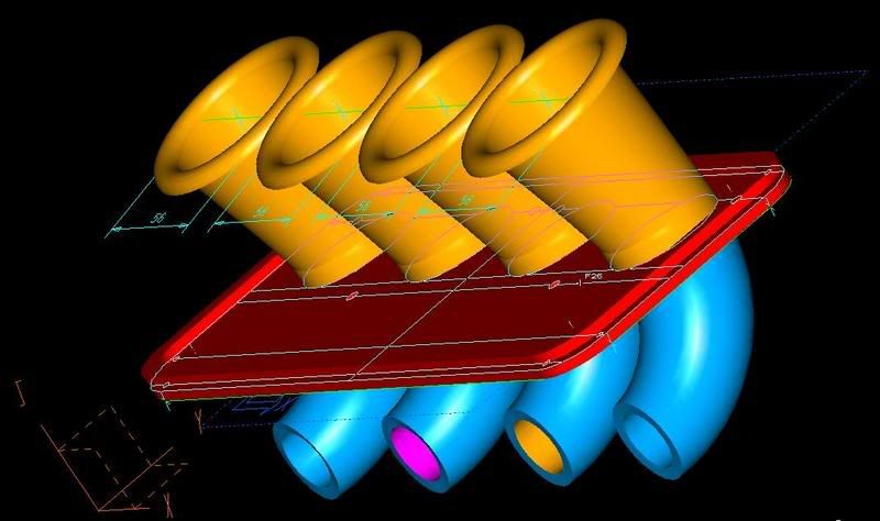
I have missed out the throttle bodies as they are known constants in dimension, so I only modelled all the parts I am making.
The back plate and flange seal I decided to machine in aluminium, well not me personally as I don’t have a CNC machine (one sec ill just check my back pocket……nope ). So I took the throttle bodies to M.J. services (the guys who did the blower flange) along with some 4mm ally plate and a design, I did ask how long it would take (thinking a couple of weeks) and they replied – “end of the day ok?”. Well it didn’t even take that long, a call two hours later and it was all done, stunning to say the least!
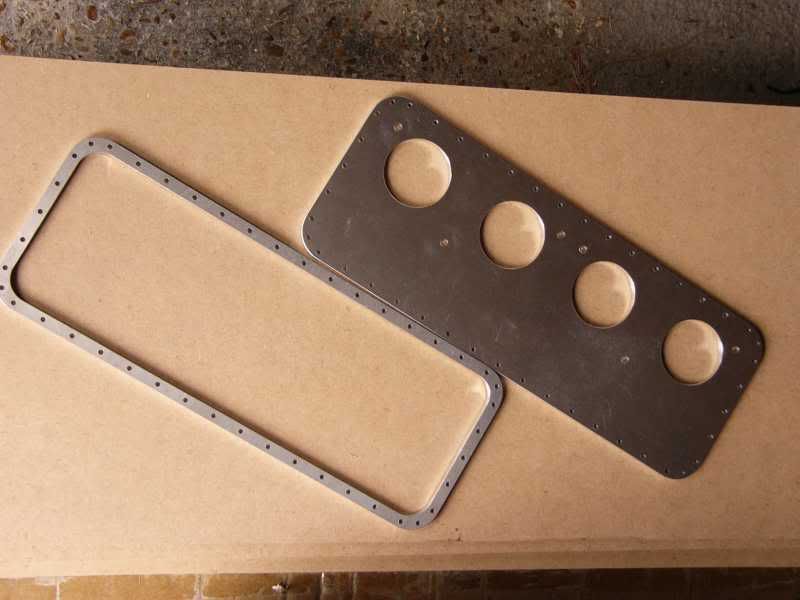
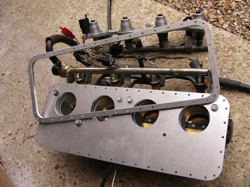
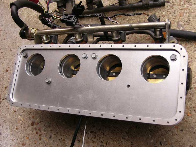
So the back plate is now done as is the sealing ring that will sandwich the plenum, this is next on the list with the trumpets close behind. I have ordered high temperature resin and carbon / glass / and aluminium coated glass (texalium) ready for moulding the trumpets and plenum chamber.
Here is the number for the machine shop chaps, cant recommend the highly enough!
M.J. Services in hampshire
tel - 01730 894449
That’s all for now, I’m waiting on stupid parcel force that make faux “promises” just like the real thing, without the commitment ahh well, mabe tomorrow!
Cheers
J
Sept 14th – Sticky Fingers!!
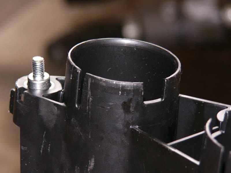
Well I’ve started making parts for the plenum and trumpets, I started with the trumpet original trumpet set up from the CBR600 throttle bodies –
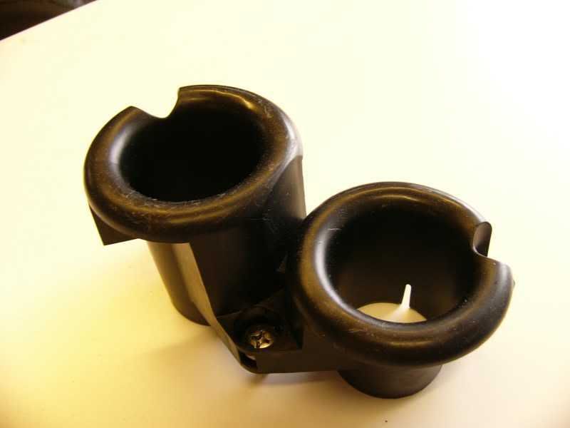
These are unequal length moulded plastic, joined at the hip. First task was to separate, this was done using the trusty Dremel and a cut off wheel. The next problem was the fact that the bell mouth has holes to accommodate a screwdriver for the attachment screws –
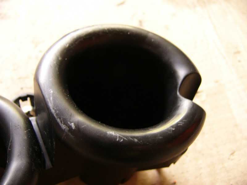
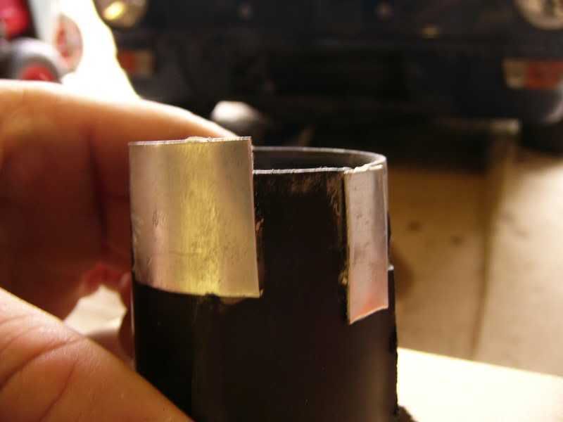
I filled the holes using quicksteel epoxy putty, and then filled using automotive body filler to get a smooth finish (this is part way through) –
At the bottom of the trumpet there are two locating slots, I glued some ally sheet over them and then filled the inside, again to make it smooth –
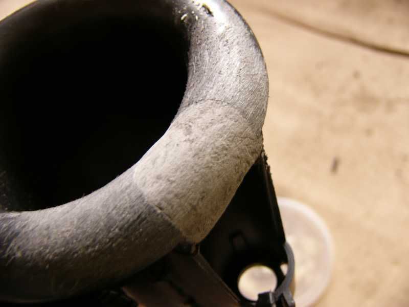
I cut a hole in a scrap piece of MDF and bedded the trumpet down onto some filler –

I then rubbed over the inside surface to key it and then primed with a few coats of white. This is as far as I got on the trumpets, tomorrow I will finish the painting and rub down/polish them ready to take a mould in Kevlar (if I can work out how to cut the bastrd stuff!)
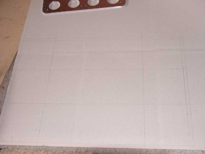
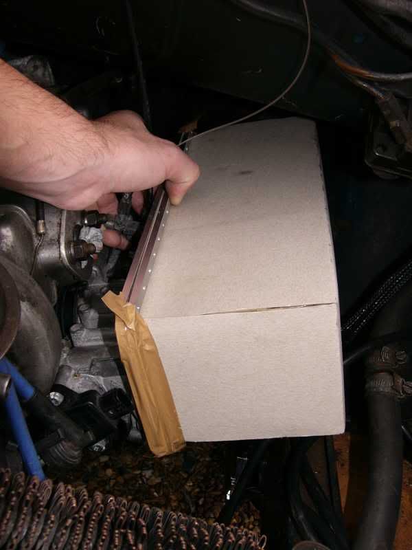
I made up a cardboard plenum to test the space both in the car and for the trumpets –
Template –
Folded and taped to back plate –
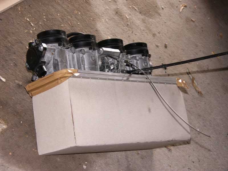
Balanced in the space available, I hope it all fits!
I started to think about the plenum construction again, and happened across this site –
http://www.bufkinengineering.com/rally%20car.htm
It’s by a chap with an Audi Quattro, lots of very interesting information including a section on the Intake manifold used for all the turbocharged Audi’s. It is a dual plenum design that has a smoothing effect on the air flowing into the main plenum. Not only will this design benefit the performance of the engine, it will actually be easier to make.
On my original design I was going to bond in a tube with a flange to one corner of the plenum, this would need a compound curve for the flange and a complex mould. With the dual plenum design the join is along a flat edge of the plenum, a much easier join.
So a quick design was done –
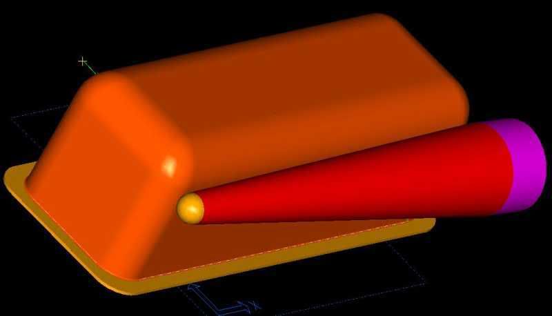
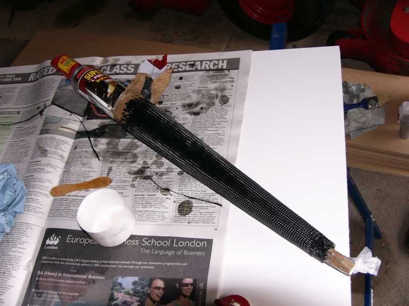
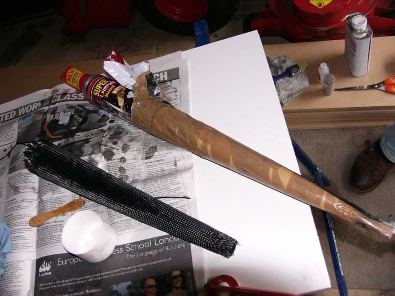
The first part to make was the cone shaped primary plenum, I made up a mould by rolling a piece of A3 paper into a cone, I covered this in packing tape, and then filled the cone with dry plaster so that it would keep its shape. I then gave this 3 coats of carnauba wax as a release agent.
I set up a table and started about getting prepared for the first layer of carbon
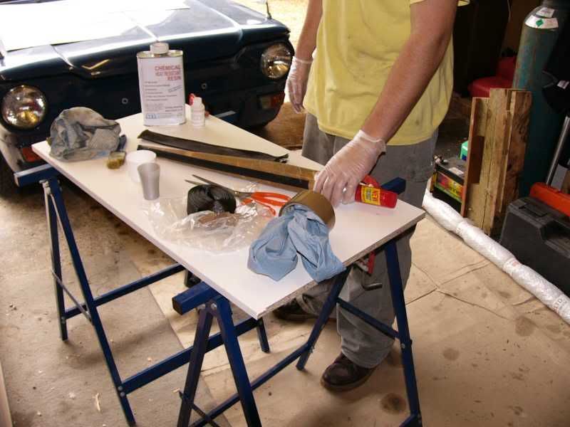
I used a carbon sleeve so there were no joins, and a high temperature chemical resistant resin, so good for the engine bay!
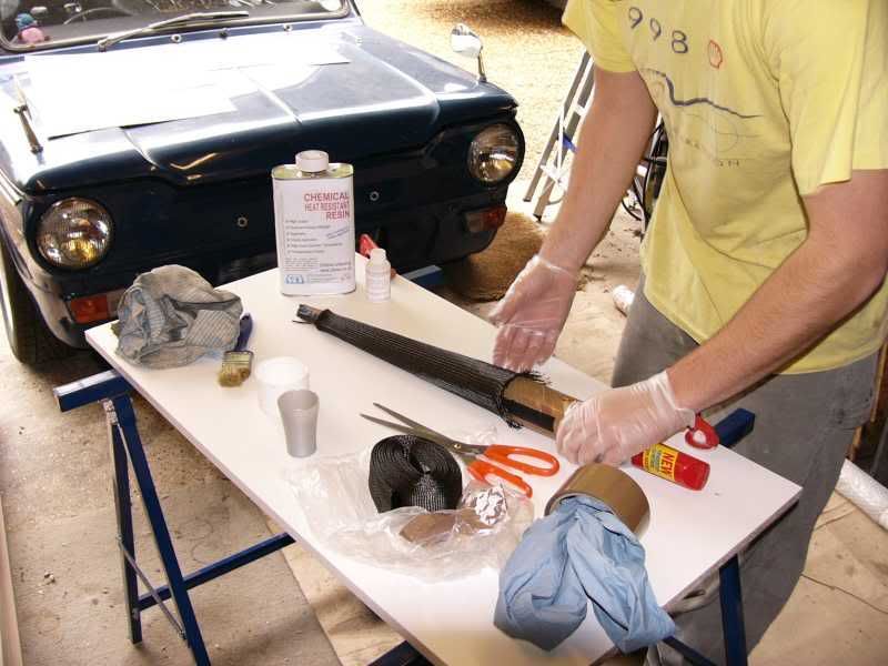
A second layer was put on and let to cure –
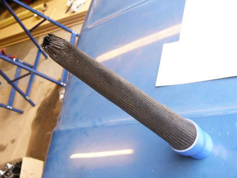
Once they were cured I decided to pull out the internal cone, this came out like it was coated in butter!
A strip of Kevlar was put around the end of the tube where the clamp was going, and then a third layer of carbon was laid over the whole lot.
I trimmed the end a checked the fitting of the silicone hose –
This is the raw piece, its going to get one last coat of resin that I can sand down smooth, and then a coat of UV proof lacquer –
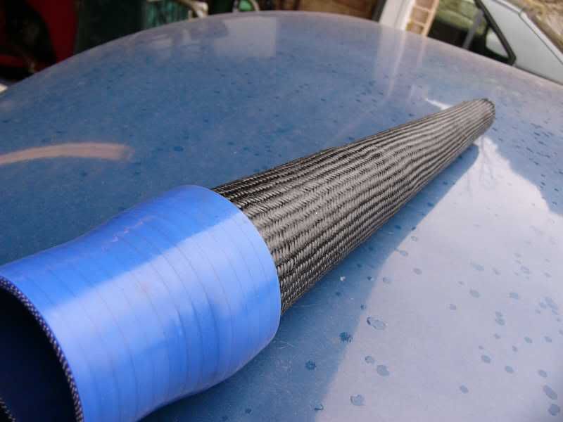
I’m going to cut a slot down one side ready for attaching to the secondary plenum then it will be finished!
I think that the trumpets are next on the list, and then making the main plenum mould.
Cheers guys and girls
J
On 5th of Sep, 2006 at 05:47pm mini13 said:
I reckon if his brains were gunpowder he couldn't blow his own hat off...
|
Paul S
8604 Posts
Member #: 573
Formerly Axel
Podland
|
|
Have you considered writing a book
When are you going to get a Mini?
Then you can CFD our inlet manifold design. I'm trying to do it but can't get the hang of AutoCAD.
Edited by Paul S on 6th Nov, 2006.
Saul Bellow - "A great deal of intelligence can be invested in ignorance when the need for illusion is deep."
Stephen Hawking - "The greatest enemy of knowledge is not ignorance, it is the illusion of knowledge."
|
dan
Forum Mod
1140 Posts
Member #: 93
Post Whore
Near Lincoln
|
|
this really is a great read, not quite sure how i've managed to miss it up till now
keep up the great work!!
|
blown_imp
223 Posts
Member #: 598
Senior Member
Gaol
|
|
Cheers guys, im almost up to date, my broken leg is really slowing me down though :(
J
On 5th of Sep, 2006 at 05:47pm mini13 said:
I reckon if his brains were gunpowder he couldn't blow his own hat off...
|
|
Home > Show Us Yours! > Supercharged and injected imp, allowed?
|
|
|
