
| Page: |
| Home > Technical Chat > Srtaight Cut drops V Standard Helical ? | |||||||
 (2)[/url] by [url=https://www.flickr.com/photos/150672766@N03/]Rod Sugden[/url], on Fli) 5988 Posts Member #: 2024 Formally Retired Rural Suffolk |
10th Oct, 2008 at 05:17:57pm
Hmmm, the damage in mike1098's case may be more due to lack of oil than all the issues we are debating.
Edited by Rod S on 10th Oct, 2008. Schrödinger's cat - so which one am I ??? |
||||||
|
Forum Mod 10979 Posts Member #: 17 ***16*** SouthPark, Colorado |
10th Oct, 2008 at 06:05:21pm
Guys, the needles don't have to 'fail' or have slop to create the thrust - remember the idler can 'slide' along the needles infinitly. Draw a FB diagram if you want to understand it better - you can simply apply a single axial force to simulate the total axial and another for the radial.
On 17th Nov, 2014 Tom Fenton said:
Sorry to say My Herpes are no better Ready to feel Ancient ??? This is 26 years old as of 2022 https://youtu.be/YQQokcoOzeY |
||||||
|
5988 Posts Member #: 2024 Formally Retired Rural Suffolk |
10th Oct, 2008 at 06:40:30pm
Dave,
Schrödinger's cat - so which one am I ??? |
||||||
|
Forum Mod 10979 Posts Member #: 17 ***16*** SouthPark, Colorado |
10th Oct, 2008 at 07:50:18pm
I am not keen on having the onus thrust onto me for the outright answer, but I'd start with a pressure fed, open chamber (one that fills, then overflows the excess volume) feed for the bearings, which runs through a decent filter.
On 17th Nov, 2014 Tom Fenton said:
Sorry to say My Herpes are no better Ready to feel Ancient ??? This is 26 years old as of 2022 https://youtu.be/YQQokcoOzeY |
||||||
 6743 Posts Member #: 828 Post Whore uranus |
12th Oct, 2008 at 11:44:16am
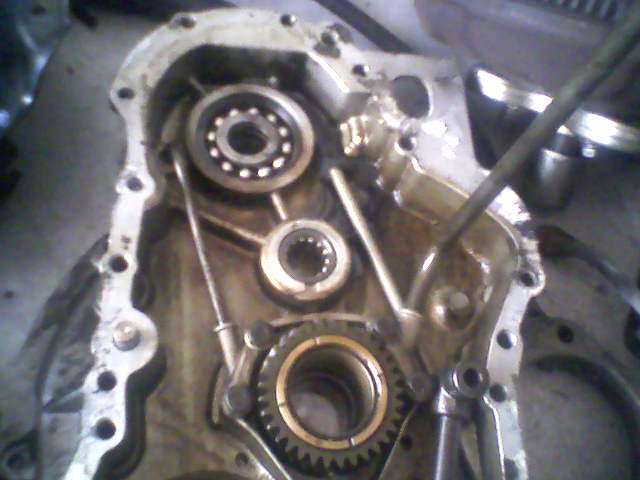
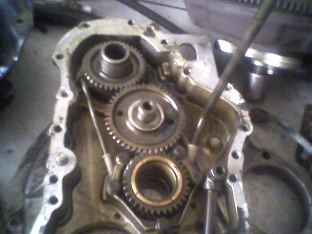
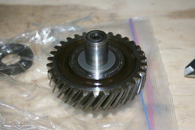
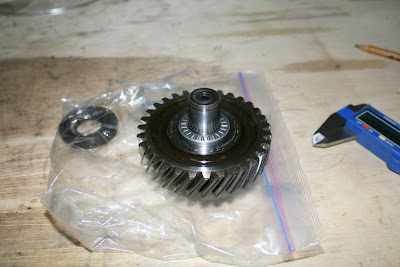
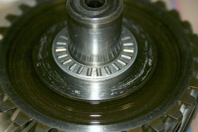
paulH i thought you might find these interesting,thy are the drop gears from an auto min box . bigger bearings and gears ,presumably to take the torque multiplication of the torque converter .
Medusa + injection = too much torque for the dyno ..https://youtu.be/qg5o0_tJxYM |
||||||
 1346 Posts Member #: 2340 Post Whore Dublin Ireland |
12th Oct, 2008 at 06:22:38pm
umm thanks robert now youv got me thinking very intresting. On 17th Feb, 2009 Rob H said:
I find the easiest way is to super glue the bolt to the end of one of my fingers. ______________________________________________________ |
||||||
|
152 Posts Member #: 2190 Advanced Member South Carolina, USA |
4th Nov, 2008 at 03:09:59am
Holy crap guys, I wish I had known this thread had been going on, the title was misleading... Rod S just pointed me to it. It might be dead now but I wanted to add my two cents.
|
||||||
|
152 Posts Member #: 2190 Advanced Member South Carolina, USA |
4th Nov, 2008 at 05:11:15am
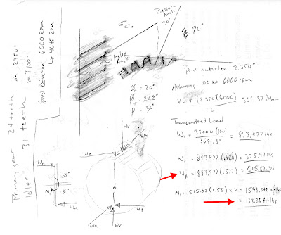
Alright, I dusted off the brain cells and came up with the following force calcs.
Edited by Mikes1098 on 8th Nov, 2008. |
||||||
|
5988 Posts Member #: 2024 Formally Retired Rural Suffolk |
4th Nov, 2008 at 07:16:43am
I'll watch with interest....
Schrödinger's cat - so which one am I ??? |
||||||
 11046 Posts Member #: 965 Post Whore Preston On The Brook |
4th Nov, 2008 at 11:04:41am
The only other problem to consider with the roller thrust bearing is how you are going to apply the correct pre load.
On 26th Oct, 2004 TurboDave16v said:
Is it A-Series only? I think it should be... So when some joey comes on here about how his 16v turbo vauxhall is great compared to ours, he can be given the 'bird'... On 26th Oct, 2004 Tom Fenton said:
Yep I agree with TD........ |
||||||
|
152 Posts Member #: 2190 Advanced Member South Carolina, USA |
7th Nov, 2008 at 01:55:15am
Moving forward⦠going to give the needle thrust bearings a go!
Edited by Mikes1098 on 8th Nov, 2008. |
||||||
|
5988 Posts Member #: 2024 Formally Retired Rural Suffolk |
7th Nov, 2008 at 07:26:13am
Very interesting...
Schrödinger's cat - so which one am I ??? |
||||||
|
6743 Posts Member #: 828 Post Whore uranus |
7th Nov, 2008 at 10:44:33am
mike , you excite me ! Medusa + injection = too much torque for the dyno ..https://youtu.be/qg5o0_tJxYM |
||||||
|
1346 Posts Member #: 2340 Post Whore Dublin Ireland |
7th Nov, 2008 at 11:06:55am
Edited by PaulH on 7th Nov, 2008. On 17th Feb, 2009 Rob H said:
I find the easiest way is to super glue the bolt to the end of one of my fingers. ______________________________________________________ |
||||||
|
Forum Mod 10979 Posts Member #: 17 ***16*** SouthPark, Colorado |
7th Nov, 2008 at 12:54:19pm
These are small thrusts for sure - especially when you consider this is a pre A+ idler.
On 17th Nov, 2014 Tom Fenton said:
Sorry to say My Herpes are no better Ready to feel Ancient ??? This is 26 years old as of 2022 https://youtu.be/YQQokcoOzeY |
||||||
|
6743 Posts Member #: 828 Post Whore uranus |
7th Nov, 2008 at 06:32:19pm
On 7th Nov, 2008 PaulH said:
 we will just draw a discreet veil over that one Robert we will just draw a discreet veil over that one Robertum.... yes . probably best :$ :) Medusa + injection = too much torque for the dyno ..https://youtu.be/qg5o0_tJxYM |
||||||
|
4314 Posts Member #: 700 Formerly British Open Classic The West Country |
7th Nov, 2008 at 10:17:10pm
On 8th Oct, 2008 TurboDave said:
Hence, as regards the single row-ball bearing at the first motion shaft - this has a theoretical lower loading when the drivetrain is all helical, or all SC - and a higher overall loading when SC and helical are mixed. Dave, surely this is the case in a stock gear box when you pull away in first? (helical drops, helical box, but SC first gear) also first tends to see more torque (assuming my limited understanding is correct). Rob PS sorry if you've already covered this, it's taken me 2 hours reading and I still haven't got to grips with everything in this thread, yet. Isambard Kingdom Brunel said:
Nothing is impossible if you are an Engineer |
||||||
|
628 Posts Member #: 1064 Formally Whyte_ben Horndean, Hampshire |
7th Nov, 2008 at 10:36:27pm
On 7th Nov, 2008 robert said:
On 7th Nov, 2008 PaulH said:
we will just draw a discreet veil over that one Robertum.... yes . probably best :$ :) Never!!!!! Edited by Ben. on 7th Nov, 2008.
|
||||||
 85 Posts Member #: 2234 Advanced Member Palm Beach Gardens, Florida |
8th Nov, 2008 at 12:02:34am
From the Crazy Idea department...the original thrust washers were up against the side faces of the gear. The shaft stubs sticking out of the gear have flat faces at their ends which could similarly take up some of the thrust load. |
||||||
|
152 Posts Member #: 2190 Advanced Member South Carolina, USA |
8th Nov, 2008 at 03:53:08am
On 7th Nov, 2008 Rod S said:
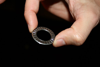
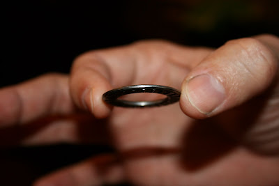
The main thing that stands out from the photos is just how small a diameter it is compared to the original washers so, when your hardened washer (that makes the outer part of the bearing) goes up against the aluminium it is sitting on a much smaller area than the previous thrust washer did... What if it rotates relative to the aluminium ??? If it did, the wear rate would be much higher than the previous washer. Have you considered anyway of locking it so it can't turn ??? And final practicality - how will you set the clearance ??? Additional shims behind one of the washers or just very accurate machining of the aluminium ??? None of that is meant to be negative, please don't take it that way, I'm just thinking of the practicalities of making it work. Final question(s), what size bearing is it, is it imperial or metric, was it an exact fit on the shaft diameter... I then need to find out if there is an appropriate size for the A+ shaft. No offense at all Rod⦠I welcome other opinions and thoughts⦠As far as the hardened washer rotating relative the aluminum⦠hopefully this wonât happen. There should be very little rotational force being put into the washer. Theoretically, the surface area of the roller that makes contact with the washer would be basically stationary relative to the washer (if that makes sense). However, if the rollers ever bind or slip then you would have the potential of the washer rotating. If that occurs your point is very valid and it will probably dig into the case. I am sort of going on the idea that these bearings are probably frequently used in other aluminum housings and the washers by design are never locked⦠dunno on this one, might just have to keep my fingers crossed. As far as clearance⦠Donât think I am good enough to even come close to accurately machine the aluminum to provide the proper clearance. This will be accomplished by shim washers. This is where I am at in the project. I think I need a .006â shim, but I want to reassemble everything just to measure twice before I order it. My shaft and bearing were imperialâ¦exactly 0.750â. On 8th Nov, 2008 scooperman said:
From the Crazy Idea department...the original thrust washers were up against the side faces of the gear. The shaft stubs sticking out of the gear have flat faces at their ends which could similarly take up some of the thrust load. Scooperman, donât think the ends of the idler gear shaft make contact with the bottom of the bore in the flywheel housing and gearbox side has through hole. Robert, well ummm, not sure what to say.... 
Edited by Mikes1098 on 8th Nov, 2008. |
||||||
|
5988 Posts Member #: 2024 Formally Retired Rural Suffolk |
8th Nov, 2008 at 08:29:18am
Good stuff....
Schrödinger's cat - so which one am I ??? |
||||||
|
152 Posts Member #: 2190 Advanced Member South Carolina, USA |
11th Nov, 2008 at 03:55:29pm
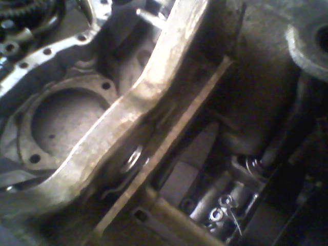
A small overlook that I found when assembling the thrust bearings... the bore for the radial needle bearings will leave the thrust washer unsupported for about half the length of the roller :(
|
||||||
|
5988 Posts Member #: 2024 Formally Retired Rural Suffolk |
11th Nov, 2008 at 04:06:06pm
Maybe an opportunity to recess the outer washer(s) into the casings ??? Schrödinger's cat - so which one am I ??? |
||||||
|
152 Posts Member #: 2190 Advanced Member South Carolina, USA |
11th Nov, 2008 at 04:42:52pm
Yeah, on the cover side...but the gearbox side is all built so it will go without the recess.
|
||||||
 1424 Posts Member #: 2810 Formally spanner181187 Dublin, Ireland |
29th Apr, 2009 at 09:17:29pm
I haven't checked the SKF and Timken catalogues yet but is there any reason that ball bearing thrusts have not been mentioned yet? I will read over the technical data on them soon but off hand they have a high speed rating. We used to use them as an equivelent to a clutch release bearing in radio controlled cars with engine speeds of ~50K RPM. They required very little lubrication in this application. Also, due to their low profile (OD - ID) maybe 2 could be used together with one outside the other. The only glaringly obvious disadvantage (to me anyway On 12th Nov, 2009 Paul S said:
I think Gary OS has taken over my role as the forum smart arse  On 30th Apr, 2010 Rod S said:
Gary's description is best |
||||||
| Home > Technical Chat > Srtaight Cut drops V Standard Helical ? | |||||||
|
|||||||


 ) over needle rollers is the fact that they would be wider.
| Page: |