Donations towards server fund so far this month.

 
£0.00 / £100.00 per month
Page:
Home > A-Series EFI / Injection > New inlet manifold - now with shiny new engine

Graham T

User Avatar

608 Posts
Member #: 1106
Post Whore

Hungerford, Berks

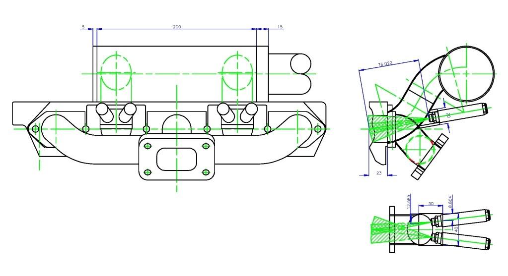
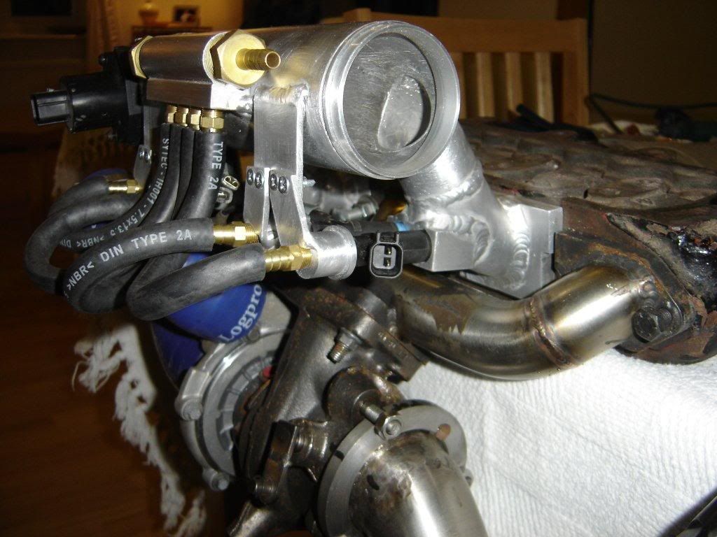
Hello all, Just thought I'd share the progress I have made so far with my new inlet manifold for my 1312 turbo EFI build. As well as asking for a bit of fitting advice.


Following on from the testing I did previously with staged injection, I now have the 4 injectors positioned as best I can, pointing into the centre of the inlet ports. The injectors are mounted 10 degrees off the horizontal and at an angle of 7 degrees each off the port centre line, which I hope will negate the problems I had with the modified MPI manifold.
The angle off the inlet centre line also gives me the room to use 1 large body injector and 1 slim body injector on each inlet tract, if my current selected thin bodied 63Lbs/hr and 82Lbs/hr injectors are not large enough for the power output I am aiming for.


To start with I will set up the inner most injectors as the primary injectors and the outer injectors the staged, larger injectors. My thinking is that IF there is any influence from the spray pattern direction, the inner injectors would tend to direct fuel to the outer cylinders, hence reducing the VE table offsets that I currently have set to get even AFR distribution between the inner and out cylinders. If appears that on the 998 NA, as the RPM and load increases, the offset between VE tables reduces, so any influence from directionality would be lessened when staging is active at higher loads and revs.
That’s yet to be confirmed, but it was my reasoning when deciding which injector to position in which pocket.

I’m still waiting for some material to finish of the Throttle body side of the inlet manifold, but it’s already evident that I will need to either remove the brake servo or get very creative with pipe work and TB positioning… As I want to put this in the 998 daily drive for testing before it goes on the Turbo engine, it looks like getting creative with the pipe work is the order of the day.

At the moment, my biggest concern is the waste gate actuator…
I'm trying to find room to mount the waste gate actuator and I'm struggling. I don't want to fit a baulk head box because of all the other extensive structural modifications done to the shell so far.

Would there be any problems with the actuator being fitted as below?


I'm concerned about heat transfer with the actuator mounted off of a bracket welded to no 4 exhaust manifold branch... I’m, also wondering if there would be any stress or movement that would need to be factored in?

I previously found some pictures of how others have mounted the actuator on the driver's side, but I'm struggling to find them again now.

My only other thought was mounting it lower, so that it is under the top engine stabiliser, mounted on a bracket off of the down pipe flange to the turbo, but that means a longer bracket...

thanks

Edited by Graham T on 3rd Dec, 2011.

’77 Clubman build thread
http://www.turbominis.co.uk/forums/index.php?p=vt&tid=618189

Siamese 5 port EFI testing
http://www.turbominis.co.uk/forums/index.php?p=vt&tid=611675


Paul S

User Avatar

8604 Posts
Member #: 573
Formerly Axel

Podland

That's looking good. Nicely engineered.

As for the actuator bracket, I've mounted mine off the no. 4 exhaust branch, lower than you have it, at the level of the bolts. I've extended the rod so that the actuator is above the steady.

Saul Bellow - "A great deal of intelligence can be invested in ignorance when the need for illusion is deep."
Stephen Hawking - "The greatest enemy of knowledge is not ignorance, it is the illusion of knowledge."


Brett

User Avatar

9502 Posts
Member #: 1023
Post Whore

Doncaster, South Yorkshire

fantastic work

Yes i moved to the darkside *happy*

Instagram @jdm_brett


998turbomini25

297 Posts
Member #: 2276
Senior Member

sheffield / derby

I like that! Looks really smart!


Carl S
Forum Mod

User Avatar

1927 Posts
Member #: 1761
Stalker

Bristol

That looks excellent Graham, nice work!


Rod S

User Avatar

5988 Posts
Member #: 2024
Formally Retired

Rural Suffolk

Graham,

Looks really good.

Injector angles are far better than I can achieve with injectors on top of the manifold.

Only comments,

The flange thickness looks different between exhaust and inlet at the head face - I had the same and used the really thick washers and milled down one side of them to suit but ideally the flanges should be the same thickness where the washer is. (fitting stepped washers is a real pain).

Ideally the actuator rod needs to be at 90 degrees to the wastegate arm at its mid-travel, anything too far away from 90 degrees and it may lock up as it rotates. Also, try to kep the actuator away as far as possible from the heat of the exhaust manifold/turbo outlet.

Schrödinger's cat - so which one am I ???


wolfie

User Avatar

8215 Posts
Member #: 90
Post Whore

Somewhere around Swindon

clever stuff

Crystal Sound Audio said:

Why wolfie...you should have your name as Fuckfaceshithead !


"A common mistake that people make when trying to design something completely
foolproof is to underestimate the ingenuity of complete fools."-Douglas Adams


robert

User Avatar

6744 Posts
Member #: 828
Post Whore

uranus

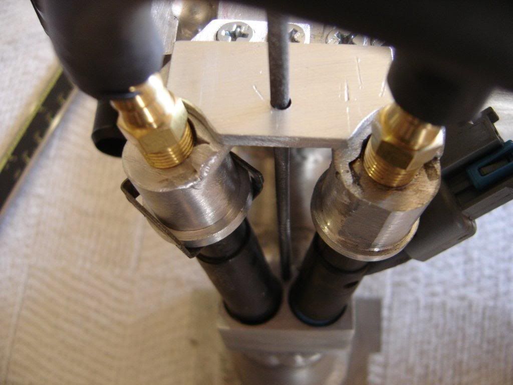
spanky looking graham ,, two things , one is id gusset the injector holding plates ,so boost pressure wont push them out ,a little triangle either side to the plenum .

wastegate rod really wants to be at a right angle to the arm ,for maximum sensitivity .

regards
robert

Medusa + injection = too much torque for the dyno ..https://youtu.be/qg5o0_tJxYM


Joe C

User Avatar

12307 Posts
Member #: 565
Carlos Fandango

Burnham-on-Crouch, Essex

re roberts point,

assuming 30psi base fuel pressure, at 15psi boost (45psi total fuel pressure) you are likly to see 10-11lb of force from each injector.

On 28th Aug, 2011 Kean said:
At the risk of being sigged...

Joe, do you have a photo of your tool?


http://www.turbominis.co.uk/forums/index.p...9064&lastpost=1

https://joe1977.imgbb.com/


Graham T

User Avatar

608 Posts
Member #: 1106
Post Whore

Hungerford, Berks

Thanks to all for the positive feedback, there is still a fair bit to do to get it functional, but just routing pipes, wiring and fitting the TB in. Hopefully the hard part is done.
Paul, I think it may have been a picture of your setup from the back that I saw previously, I can drop the actuator, I was thinking about keeping the bracket as short as possible to try to keep the stress to a minimum, but based on Rod’s comments, I guess it’s going to be a bit of a compromise.

Rod, the flange thicknesses are different. The inlet manifold flange thickness is a tad over 1mm less than the exhaust flange. I was originally planning to make stepped washers as you mention, but the Flanges of the exhaust manifold will probably need skimming as it looks like there was movement during the manufacturing process. They don’t sit flat on the head, so I may yet be able to get the flanges at the same thickness.
The waste gate arm was already modified when it arrived (Not at my request). I will need to cut it off and reset it, depending on where the actuator finally ends up…
I will offer it up in the car again tomorrow and mock up a bracket.

’77 Clubman build thread
http://www.turbominis.co.uk/forums/index.php?p=vt&tid=618189

Siamese 5 port EFI testing
http://www.turbominis.co.uk/forums/index.php?p=vt&tid=611675


Graham T

User Avatar

608 Posts
Member #: 1106
Post Whore

Hungerford, Berks

Thanks Robert, Joe.
I see your point. I’ll need to think how to do this and have it so that the injectors can still be easily removed. It’ll be easy enough to gusset the main plate that is welded to the Plenum body, but I’m not sure about the plates that are welded to the injector “caps”.

’77 Clubman build thread
http://www.turbominis.co.uk/forums/index.php?p=vt&tid=618189

Siamese 5 port EFI testing
http://www.turbominis.co.uk/forums/index.php?p=vt&tid=611675


evolotion

User Avatar

2909 Posts
Member #: 83
Post Whore

Glasgow, Scotland

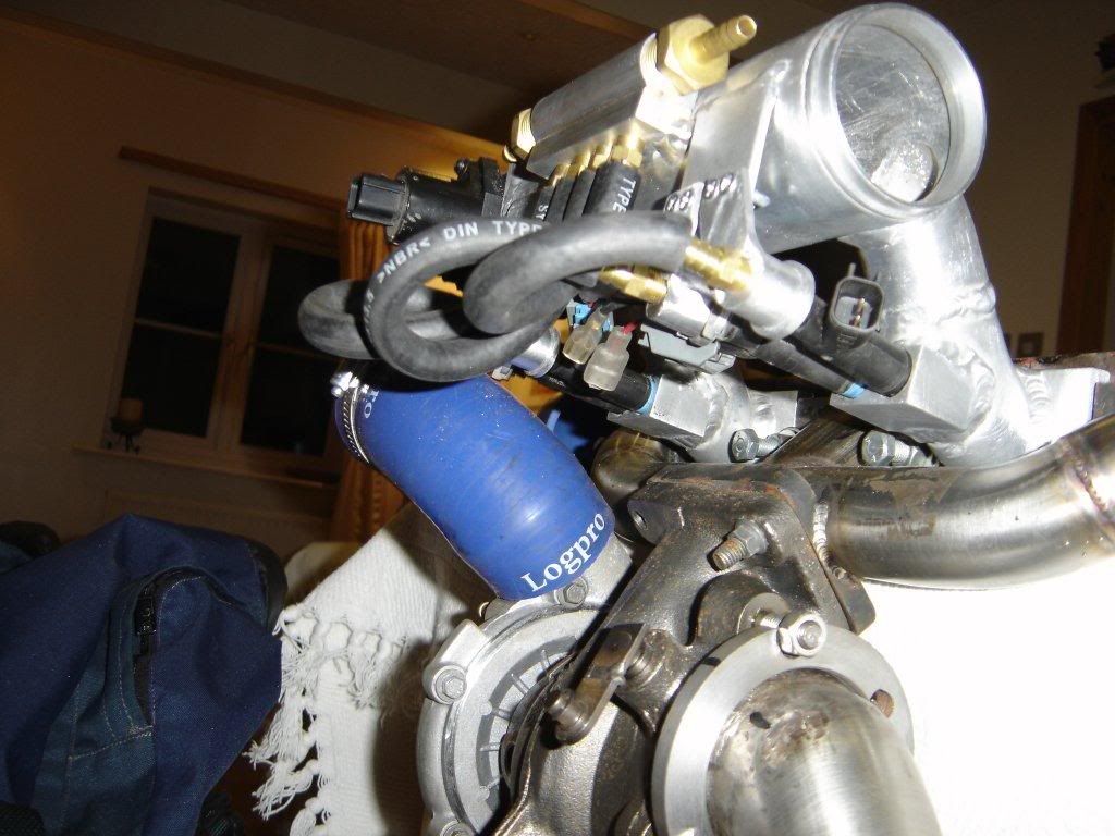
Echo roberto's comments and a heat shield between turbo and the rubber fuel hoses/injectors wouldnt hurt either, you would be stunned at the IR heat a turbo gives off and could harm the lines :) even just a simple sheet of stainless, lovely setup!

turbo 16v k-series 11.9@118.9 :)

Denis O'Brien.


Rob H

4314 Posts
Member #: 700
Formerly British Open Classic

The West Country

Looks really nice, is it worth fitting a heat shield underneath the injectors? or will it make bugger all difference?

Isambard Kingdom Brunel said:
Nothing is impossible if you are an Engineer


Graham T

User Avatar

608 Posts
Member #: 1106
Post Whore

Hungerford, Berks

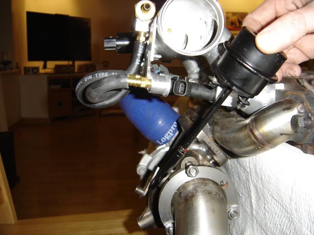
A heat shield is in the plans, I just have to work out the positioning for the 3 Lambda sensor sample chambers and associated piping first, which I can only work out once the Waste gate actuator is positioned.

And I said the hard parts were already done!

’77 Clubman build thread
http://www.turbominis.co.uk/forums/index.php?p=vt&tid=618189

Siamese 5 port EFI testing
http://www.turbominis.co.uk/forums/index.php?p=vt&tid=611675


evolotion

User Avatar

2909 Posts
Member #: 83
Post Whore

Glasgow, Scotland


On 18th Mar, 2011 Rob H said:
Looks really nice, is it worth fitting a heat shield underneath the injectors? or will it make bugger all difference?


wont make any diff to there operation per-se, my only concern is trying/enbrittlment of the hoses feeding the injectors.

turbo 16v k-series 11.9@118.9 :)

Denis O'Brien.


robert

User Avatar

6744 Posts
Member #: 828
Post Whore

uranus


On 18th Mar, 2011 Graham T said:
Thanks Robert, Joe.
I see your point. I’ll need to think how to do this and have it so that the injectors can still be easily removed. It’ll be easy enough to gusset the main plate that is welded to the Plenum body, but I’m not sure about the plates that are welded to the injector “caps”.


graham , if it helps ,heres what i did in 91 when i built the fi for the tvr ,it used a couple of straps from the top to the bottom of each injector .it looks a bit crude , but it did work .


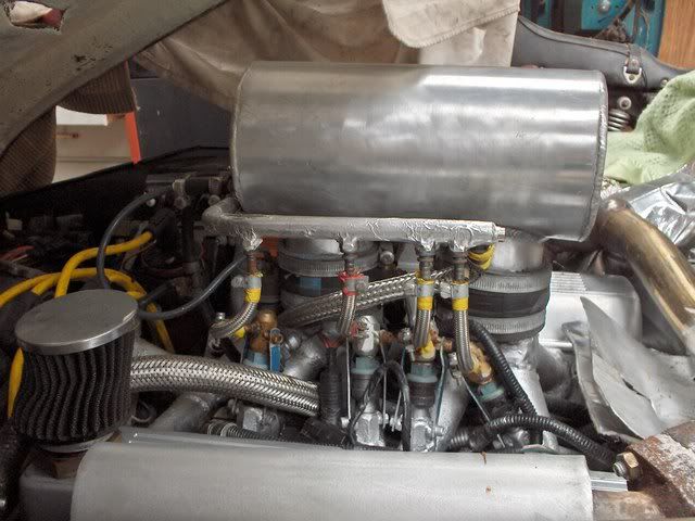
another approach may be to put a thread on the body of the injector and a thread in the mounting bung so you just screw them in .
regards
robert.

Medusa + injection = too much torque for the dyno ..https://youtu.be/qg5o0_tJxYM


Graham T

User Avatar

608 Posts
Member #: 1106
Post Whore

Hungerford, Berks

Thanks Robert. I actually saw something similar when I was searching for material for the fuel rail.
A bit like this:
http://www.himni-racing.com/index.php?main...products_id=704

I thought about it at the time, but because my injector pockets are machined at an angle to the flat of the material that they are in, I thought it too complicated to implement. And they are bloody expensive...

I now have an idea on how to strengthen the plates with you original suggestion of gussets.
It is easier to show than explain, so I’ll mock something up today.

’77 Clubman build thread
http://www.turbominis.co.uk/forums/index.php?p=vt&tid=618189

Siamese 5 port EFI testing
http://www.turbominis.co.uk/forums/index.php?p=vt&tid=611675


Rod S

User Avatar

5988 Posts
Member #: 2024
Formally Retired

Rural Suffolk

Graham,

Looking at that "himni" design, could you not squeeze a single long thin stud (say M3 or M4) inbetween your pair of injectors and and then put a single plate bridging the two injector inlets.

As your pair of injectors are symettric a single stud and "Tee" plate would retain them both and the angle wouldn't matter.

Hard to put in words, if that doesn't make sense I'll do a sketch.

Schrödinger's cat - so which one am I ???


Graham T

User Avatar

608 Posts
Member #: 1106
Post Whore

Hungerford, Berks

Perfect sense, and easier than what I was about to try.

’77 Clubman build thread
http://www.turbominis.co.uk/forums/index.php?p=vt&tid=618189

Siamese 5 port EFI testing
http://www.turbominis.co.uk/forums/index.php?p=vt&tid=611675


Rod S

User Avatar

5988 Posts
Member #: 2024
Formally Retired

Rural Suffolk

Good,

Thinking a bit further, if the injectors are too close to each other to get a single stud in on the horizontal centreline (or if drilling/tapping risks breaking into the pockets as they converge) you could use two, still inbetween the injectors but each offset vertically (one upwards and one downwards) by an equal amount - so it would still be symettrical with respect to the injector pair and still be in a "Tee" configuration.

Schrödinger's cat - so which one am I ???


Graham T

User Avatar

608 Posts
Member #: 1106
Post Whore

Hungerford, Berks

I think I can tap a small M3 hole in the injector pocket block, just...


’77 Clubman build thread
http://www.turbominis.co.uk/forums/index.php?p=vt&tid=618189

Siamese 5 port EFI testing
http://www.turbominis.co.uk/forums/index.php?p=vt&tid=611675


sturgeo

857 Posts
Member #: 1778
Post Whore

Northants

I like it, what diameter is the plenum?


Graham T

User Avatar

608 Posts
Member #: 1106
Post Whore

Hungerford, Berks

Thanks Sturgeo.

It's 63mm OD, 200mm long.

’77 Clubman build thread
http://www.turbominis.co.uk/forums/index.php?p=vt&tid=618189

Siamese 5 port EFI testing
http://www.turbominis.co.uk/forums/index.php?p=vt&tid=611675


Paul S

User Avatar

8604 Posts
Member #: 573
Formerly Axel

Podland

Found the picture of my actuator:

Edited by Paul S on 19th Mar, 2011.

Saul Bellow - "A great deal of intelligence can be invested in ignorance when the need for illusion is deep."
Stephen Hawking - "The greatest enemy of knowledge is not ignorance, it is the illusion of knowledge."


sturgeo

857 Posts
Member #: 1778
Post Whore

Northants

You might just be able to squeeze the TB on the end with the servo in place. I was working out the other night if I need to ditch my servo and if you use one of the compact TBs you could fit it in.

Home > A-Series EFI / Injection > New inlet manifold - now with shiny new engine
Users viewing this thread: none. (+ 1 Guests)   Next ->
To post messages you must be logged in!
Username: Password:
Page: