
| Page: |
| Home > FAQ / Knowledge > Building an RTS clutch - Photo Heavy | |||||||
|
313 Posts Member #: 9367 Senior Member Derby |
8th Apr, 2013 at 07:40:07pm
So when you measure up for the additional length you just measure the thickness of the two springs anywhere on the spring or do you want to do it where the bolt goes through? Do you measure the pivot rings as well and add in the top one too or is that not necessary?
On 5th Apr, 2013 Joe C said:
Yep, springs range from 1.6mm to 2.4mm and IIRC Ive seen 2.2 and 3 mm pivot rings. |
||||||
 12307 Posts Member #: 565 Carlos Fandango Burnham-on-Crouch, Essex |
8th Apr, 2013 at 07:50:12pm
yep the springs seem to be the same thickness all the way across, Ive just measured them at the edge,
On 28th Aug, 2011 Kean said:
At the risk of being sigged... Joe, do you have a photo of your tool? http://www.turbominis.co.uk/forums/index.p...9064&lastpost=1 https://joe1977.imgbb.com/ |
||||||
|
313 Posts Member #: 9367 Senior Member Derby |
8th Apr, 2013 at 07:56:26pm
Just out of interest why do you add in the thickness of the bottom pivot ring as that is below the original diagphram so isn't this surely covered by the thickness of the original spacer? |
||||||
|
12307 Posts Member #: 565 Carlos Fandango Burnham-on-Crouch, Essex |
8th Apr, 2013 at 08:23:34pm
look at the diagram on the previous page, thats how it is on the flywheels that I have seen,
On 28th Aug, 2011 Kean said:
At the risk of being sigged... Joe, do you have a photo of your tool? http://www.turbominis.co.uk/forums/index.p...9064&lastpost=1 https://joe1977.imgbb.com/ |
||||||
|
313 Posts Member #: 9367 Senior Member Derby |
8th Apr, 2013 at 08:38:34pm
Sorry I thought you meant all of those on top of the original spacer. I understand it now. |
||||||
 11046 Posts Member #: 965 Post Whore Preston On The Brook |
8th Apr, 2013 at 11:34:17pm
Spacer length is the sum of the component parts that make up the 'stack' those are as Joe says, the two wire rings and the two springs. Simples :) On 26th Oct, 2004 TurboDave16v said:
Is it A-Series only? I think it should be... So when some joey comes on here about how his 16v turbo vauxhall is great compared to ours, he can be given the 'bird'... On 26th Oct, 2004 Tom Fenton said:
Yep I agree with TD........ |
||||||
 975 Posts Member #: 3228 Post Whore North of the Netherlands |
1st Jul, 2014 at 10:08:56am
Seems the trend is now to not tap the rivet holes anymore but drill though and nut and bolt the assy together(?)
Dazed and Confused.... |
||||||
 1030 Posts Member #: 1291 Post Whore Suffolk / Birmingham |
1st Jul, 2014 at 01:23:12pm
Theres no room for that on my AP setup. |
||||||
|
975 Posts Member #: 3228 Post Whore North of the Netherlands |
6th Jul, 2014 at 08:10:48am
Bit confused now.
Dazed and Confused.... |
||||||
|
1030 Posts Member #: 1291 Post Whore Suffolk / Birmingham |
6th Jul, 2014 at 09:00:50am
Possibly. I know on mine theres only a few mm of space before the pressure plate. Might just squeeze dome heads in there or maybe turn most of the head off a cap head and weld them captive? Sprocket will know im sure :) |
||||||
|
12307 Posts Member #: 565 Carlos Fandango Burnham-on-Crouch, Essex |
6th Jul, 2014 at 11:52:01am
I think he countersunk them. On 28th Aug, 2011 Kean said:
At the risk of being sigged... Joe, do you have a photo of your tool? http://www.turbominis.co.uk/forums/index.p...9064&lastpost=1 https://joe1977.imgbb.com/ |
||||||
 2094 Posts Member #: 9894 Post Whore Dorking |
6th Feb, 2015 at 11:30:35pm
Anybody find out what the latest bolt technique is?
|
||||||
|
65 Posts Member #: 9646 Advanced Member Bristol England |
7th Feb, 2015 at 07:51:24pm
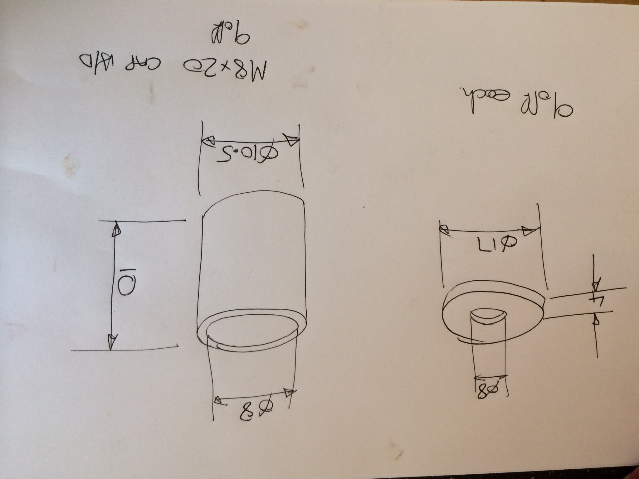
I built one last year and just tapped M8 used high tensile cap heads and some loctite high strength thread lock. I think I posted some pics somewhere I've got a sketch of the spacers and washers too if that helps. |
||||||
|
1030 Posts Member #: 1291 Post Whore Suffolk / Birmingham |
7th Feb, 2015 at 10:12:22pm
Mine is just tapped and has been alright but i reckon c/s is a more reliable approach. |
||||||
|
2094 Posts Member #: 9894 Post Whore Dorking |
7th Feb, 2015 at 10:56:00pm
Thats what i'm thinking slater. I'd just like an idea of how someone else has done it before comiting.
|
||||||
|
12307 Posts Member #: 565 Carlos Fandango Burnham-on-Crouch, Essex |
7th Feb, 2015 at 11:07:36pm
tapping is fine on the AP ones as the rivet hole is a little below tapping size so you can just bang a tap through and get a nice snug thread, but on the valeo ones Ive seen the hole is a bit baggy, so the thread is not ideal so they would be best with countersunk screws and nuts on the outside. On 28th Aug, 2011 Kean said:
At the risk of being sigged... Joe, do you have a photo of your tool? http://www.turbominis.co.uk/forums/index.p...9064&lastpost=1 https://joe1977.imgbb.com/ |
||||||
|
65 Posts Member #: 9646 Advanced Member Bristol England |
11th Feb, 2015 at 08:53:33pm
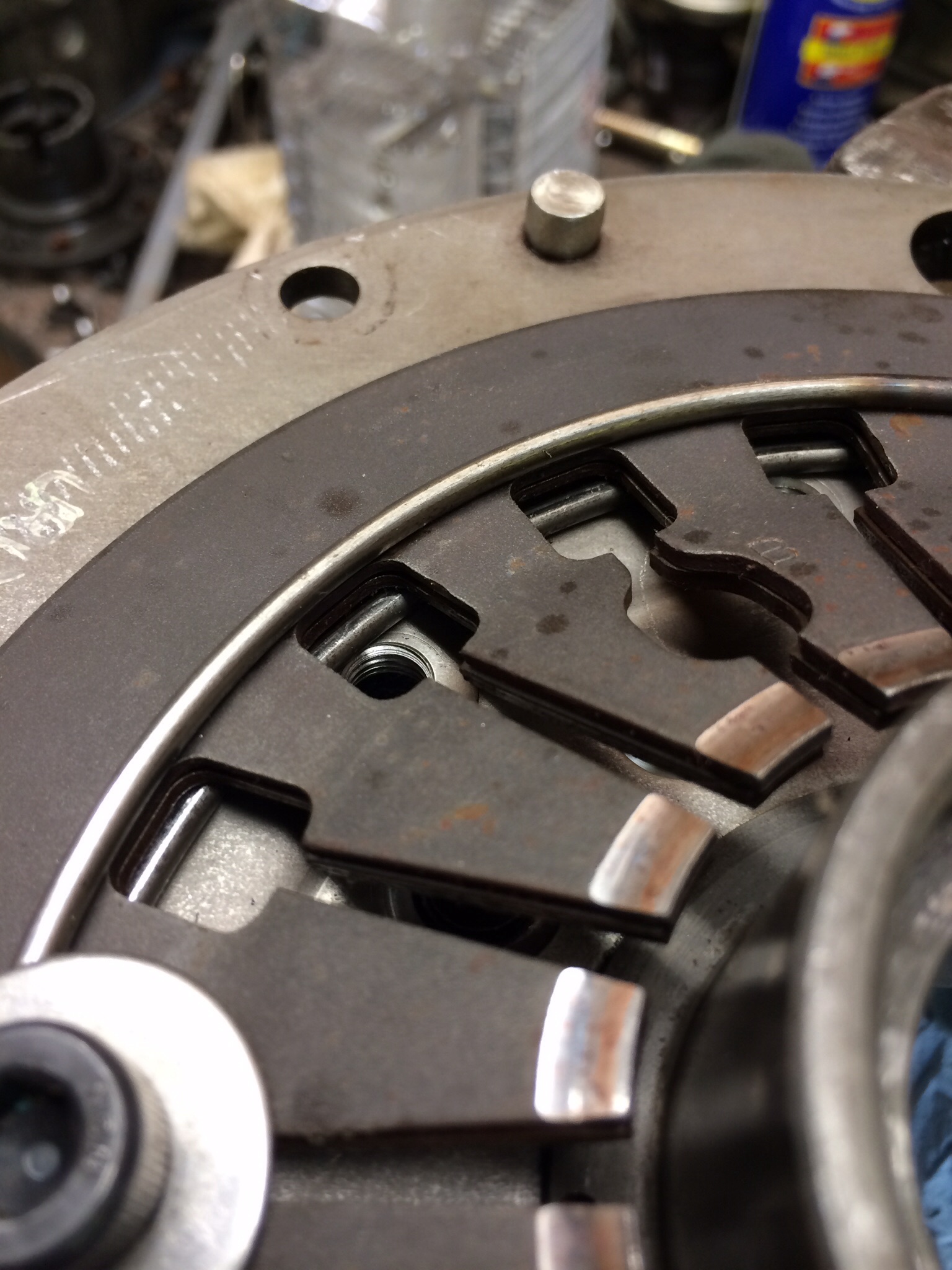
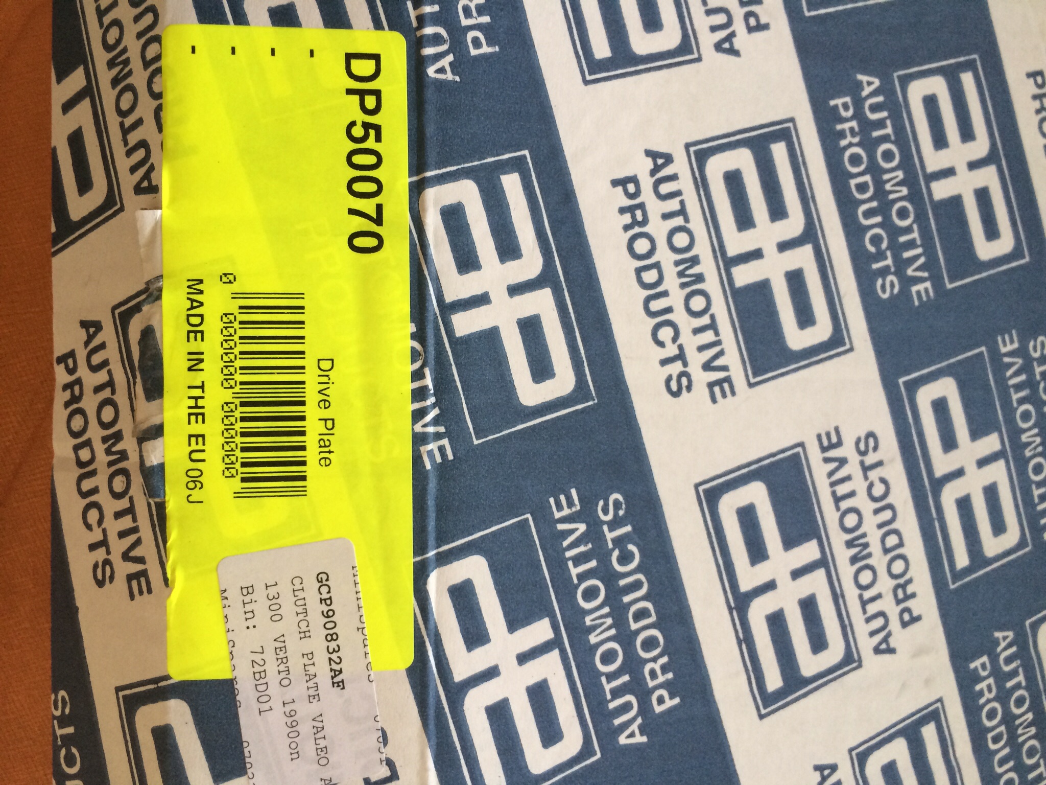
Jonny, here's some pics, as you can see I used Valeo pressure plates (used ones) and as Joe said the holes are bigger than the tapping size for M8, the one I used was 7mm, only 0.2mm bigger than it should be for M8 so I used high strength loctite too, the upsidedown drawing shows the spacers (length equals the total of the two spring plates and the two pivot rings (double check yours before manufacture)) and washers that replace the removed rivets, the washers replace the triangular shaped rivet heads, When I made the bits I made sure the spacers were all exactly the same length just to make sure the pressure release was equal all the way around ( as you can imagine the rivet, now bolt with washer and spacer, is at the pivot point of the movement. And the box is the new friction disc I used from mini spares 190mm. It is a brilliant mod, the grip is amazing, my original clutch started slipping once I pushed past 12psi, I've ran up to 17psi so far and the clutch is spot on. For science per purposes, the old pressure plate measured only 1 mm thinner than the new one and was no way near worn out. The flywheel and pressure plate surfaces are the same ones before and after the mod, although both in good condition. Edited by Nick king on 11th Feb, 2015. |
||||||
|
11046 Posts Member #: 965 Post Whore Preston On The Brook |
11th Feb, 2015 at 09:35:48pm
I use 1/4" NAS bolts which have a low head. Depending on the clutch parts used, it is sometimes just a matter of running the pressure plate in the lathe to give the bolt heads a little clearance.
On 26th Oct, 2004 TurboDave16v said:
Is it A-Series only? I think it should be... So when some joey comes on here about how his 16v turbo vauxhall is great compared to ours, he can be given the 'bird'... On 26th Oct, 2004 Tom Fenton said:
Yep I agree with TD........ |
||||||
|
65 Posts Member #: 9646 Advanced Member Bristol England |
11th Feb, 2015 at 09:43:57pm
Sprocket I'm confused. Clearance where for what? Have I over looked something?
Edited by Nick king on 11th Feb, 2015. |
||||||
|
11046 Posts Member #: 965 Post Whore Preston On The Brook |
11th Feb, 2015 at 10:36:06pm
The big advantage with the 1/4" bolts is that you need not drill anything more that the rivets to dissassemble the clutch parts. the holes in the plate just so happen to be 1/4" On 26th Oct, 2004 TurboDave16v said:
Is it A-Series only? I think it should be... So when some joey comes on here about how his 16v turbo vauxhall is great compared to ours, he can be given the 'bird'... On 26th Oct, 2004 Tom Fenton said:
Yep I agree with TD........ |
||||||
|
2094 Posts Member #: 9894 Post Whore Dorking |
12th Feb, 2015 at 09:40:28am
Thank you very much for all the info guys. I think I'll use your idea Sprocket as from an engineering perspective it makes better sense to nut and bolt it. :). |
||||||
 1751 Posts Member #: 10190 Post Whore belgium |
13th Feb, 2016 at 10:20:35pm
Okey. Not want to start a new tread to keep it all clean here.
you can do anything if you set your mind to it...
|
||||||
|
1751 Posts Member #: 10190 Post Whore belgium |
14th Feb, 2016 at 12:43:34pm
ow wait i get it... its so that you can not tighten the bolts further then needed right? you can do anything if you set your mind to it...
|
||||||
|
2094 Posts Member #: 9894 Post Whore Dorking |
14th Feb, 2016 at 12:46:17pm
You need the spacers and you are correct with the length. |
||||||
|
1751 Posts Member #: 10190 Post Whore belgium |
14th Feb, 2016 at 01:07:26pm
On 14th Feb, 2016 jonny f said:
You need the spacers and you are correct with the length. you can do anything if you set your mind to it...
|
||||||
| Home > FAQ / Knowledge > Building an RTS clutch - Photo Heavy | |||||||
|
|||||||
 but then 1/4 vs M8..........horses for courses


| Page: |