
| Page: |
| Home > Show Us Yours! > Turbo Cooper - floor repairs | |||||||
 1750 Posts Member #: 10190 Post Whore belgium |
6th Feb, 2015 at 11:47:18am
Cool tread. You give me courage again for my turbo engine. you can do anything if you set your mind to it...
|
||||||
|
696 Posts Member #: 10034 Post Whore Birmingham |
5th Jun, 2015 at 09:04:34pm
I've spent way too much time distracted with this and trying to get it to work and although it's nowhere near complete, it pretty much does what it's supposed to, so I'm calling it done...
Edited by PhilR on 2nd Feb, 2016. |
||||||
|
1750 Posts Member #: 10190 Post Whore belgium |
5th Jun, 2015 at 10:27:14pm
On 5th Jun, 2015 PhilR said:
Built a dynamic balancer. I went through half a dozen iterations and this is what worked. This afternoon I balanced my clutch well within 1 gram (was 15g out). 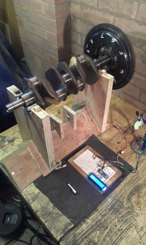
) Thats cool how does it work or mesure the unbalance? By the weight hanging over to 1 side? you can do anything if you set your mind to it...
|
||||||
 2091 Posts Member #: 9894 Post Whore Dorking |
5th Jun, 2015 at 11:01:43pm
That looks clever!
|
||||||
|
696 Posts Member #: 10034 Post Whore Birmingham |
7th Jun, 2015 at 09:14:45pm
The crank sits in v-grooves made from blocks of PTFE. These supports rest snugly against piezo transducers. When an imbalanced crank rotates it tries to rock the supports from side to side and transducers detect the pressure caused by this and create an electrical signal. At the moment, I'm just using this signal to trigger a 12W LED strobe to show me where the imbalance is. I can then add trial weights (magnets), or cut metal away and retest. The micro-controller and screen aren't really doing much in this version.
|
||||||
|
696 Posts Member #: 10034 Post Whore Birmingham |
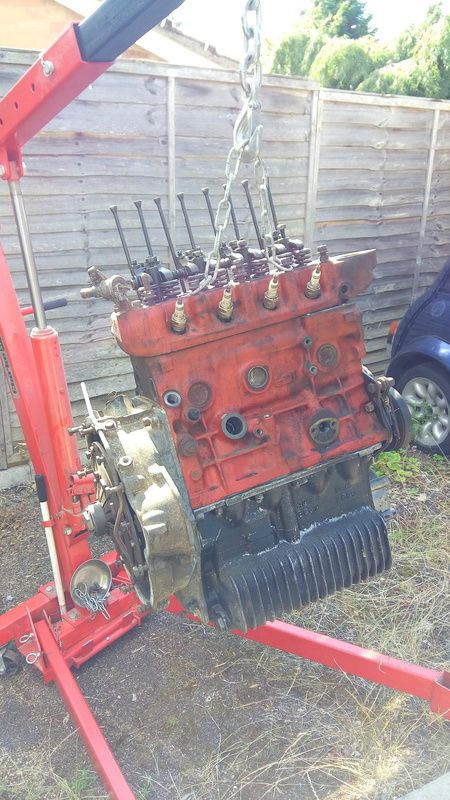
23rd Jul, 2015 at 10:50:52am
Last month had ups and downs. I've done so much work to get the 998 engine to the spec I want, but every time I complete one job, I find two more !
Edited by PhilR on 10th Sep, 2015. |
||||||
|
696 Posts Member #: 10034 Post Whore Birmingham |
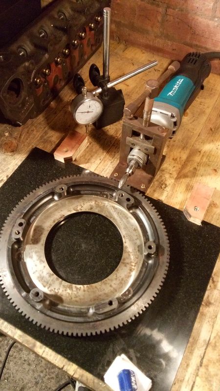
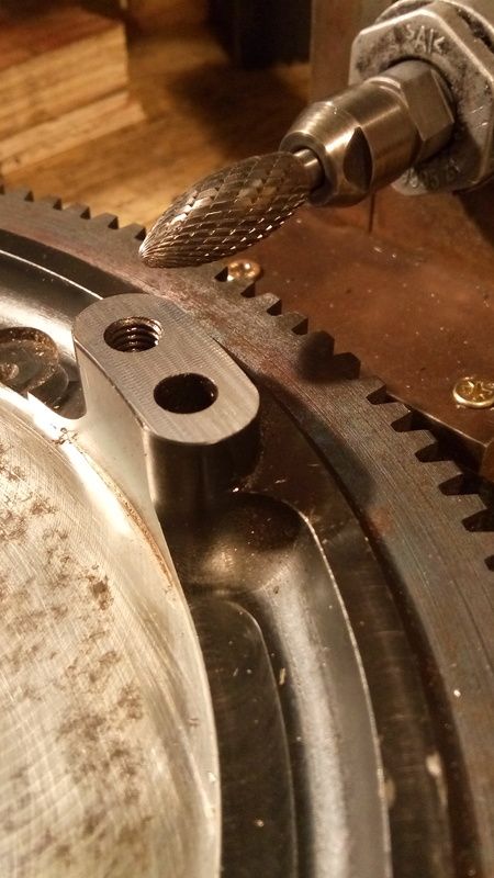
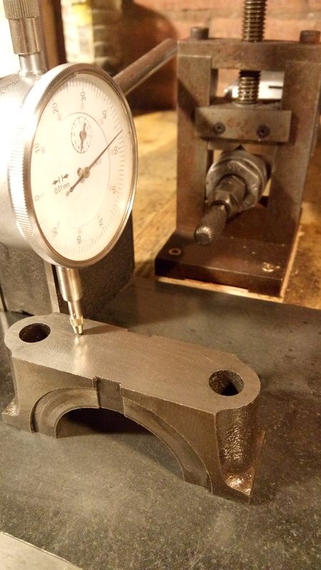
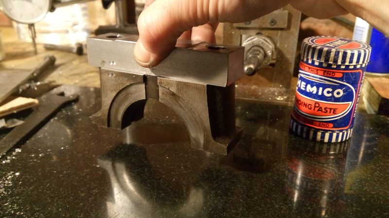
23rd Jul, 2015 at 11:20:12am
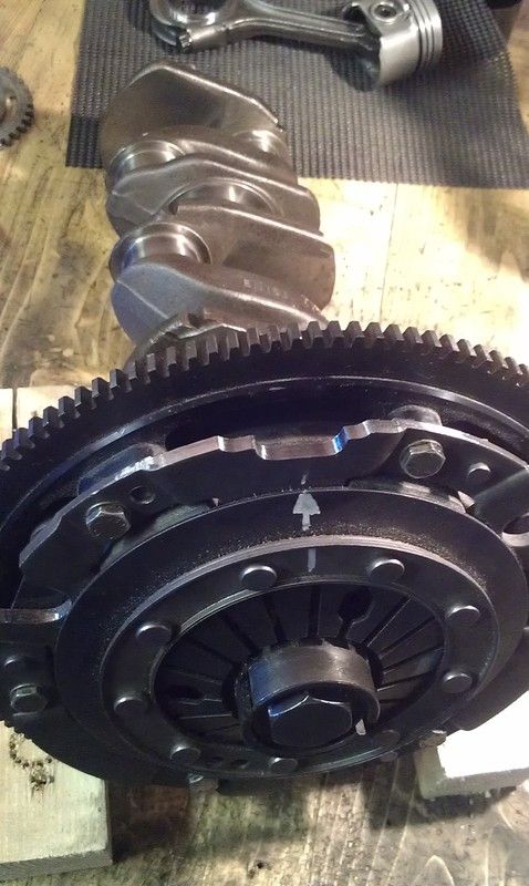
Swapping from 998 to 1275, I was concerned that the clutch would be on the limit. I measured the new flywheel against some old ones and it looked like the pillars were 0.35mm higher than they should be, so I planned to trim them down to make sure the clutch plate would be clamped down correctly. I trimmed the pillars with this:
Edited by PhilR on 5th Feb, 2016. |
||||||
|
696 Posts Member #: 10034 Post Whore Birmingham |
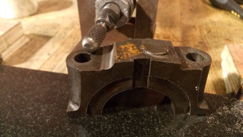
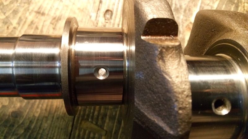
24th Jul, 2015 at 10:11:54pm
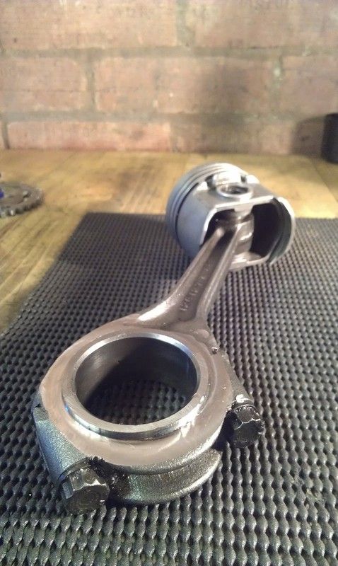
Through-drilled the mains (hand drilled of course Edited by PhilR on 5th Feb, 2016. |
||||||
|
696 Posts Member #: 10034 Post Whore Birmingham |
13th Oct, 2015 at 04:00:09pm
Slowly getting there... ticked lots of little jobs off and engine is pretty much ready to be installed. Fingers crossed and it'll be fired up this week Edited by PhilR on 13th Oct, 2015. |
||||||
 (2)[/url] by [url=https://www.flickr.com/photos/150672766@N03/]Rod Sugden[/url], on Fli) 5988 Posts Member #: 2024 Formally Retired Rural Suffolk |
14th Oct, 2015 at 07:17:32am
Looking good.
Schrödinger's cat - so which one am I ??? |
||||||
|
696 Posts Member #: 10034 Post Whore Birmingham |
14th Oct, 2015 at 10:19:22am
Thanks Rod.
Edited by PhilR on 14th Oct, 2015. |
||||||
|
5988 Posts Member #: 2024 Formally Retired Rural Suffolk |
14th Oct, 2015 at 03:20:12pm
Phil,
On 14th Oct, 2015 PhilR said:
I think you previously asked Alan whether he could do I2C output on the SLC controllers?? I'm not convinced the answer is as straight forward as 'No, there isn't enough memory' as I've had a quick play with the firmware and think a good compromise may be possible. Let me know what you think. If you have a compromise in mind I'd be interested to know what it is. The question to Alan and his reply is here. https://groups.google.com/forum/#!category-...ree/f1EHJiJF8IQ I'm not a code/firmware person at all, so way out of my comfort zone, I work more with the hardware. Taking his answer at face value it may be (a) specific to the 4.2 version that I bought to play with or (b) maybe the open source firmware (which I presmme you are looking at) may be more flexible, or © maybe the answer was based on the amount of data that a normal SLC-OEM module transmits which is what Alan knows I use in conjunction with Jean's IOx firmware. On 14th Oct, 2015 PhilR said:
The 2 pre-turbo lambda controllers will do sensor temperatures (14Point7 SLC Free + LSU4.9), although I've soldered them up to be as low profile as possible to fit inside the ECU case without the displays... Initially, I will read the AFR and heater duty cylce via Arduino analogue inputs, then push the values into the the MS2 tables via CAN bus. As long as the heater output is somewhere between fully on or off I can infer that the sensor temperature is being held steady (and perhaps even how the inner and outer temperatures compare?). I have the programmer on my desk, so I'll try a small change to the SLC firmware get it to output the temperature via one of it's free analogue outputs (or maybe just reuse the pin for the emulated narrowband output). From what I've read on another forum where Alan posts (which I found totally by random when googling something else about the 4.9LSU) Alan's heater control is PWM (fairly obvious to cut heat load on the controller boards) and PID about which he said the 4.9 algorithm is harder. Now assuming it is PWM, and you can calculate the duty cycle through your arduino measurements, I think I agree with your logic. The caution I would add is, with PID, there may be no zero or 100% duty cycle, ie, fully on or fully off may not be 0 and 100. If you can find the boundaries, it shuould certainly tell you if the LSU is being under cooled (highly unlikely in your case) or overheated. And I agree, the difference in PWM duty cycles should show the difference which I would expect to be the centre one requires less electrical heat as I see (and as Paul did previously) the centre exhaust is a lot hotter under load. If you can get the temperatures out analogue by modifying the firmware, that sounds good. But, as Alan already puts it to the small LCD display, can't you just put a small cable to the outside from his pin header to that part of the display ? I haven't actually got my 14point7 free mdule in front of me at the moment (read on) but, from what I remember, it should be quite easy with an IDC connector with a ribbon cable jjst stripped down to what you need. A word of caution on the 4.9 LSUs. Graham T has killed 3 so far with them in low temperature sample chambers. I'm not sure if the 3rd is 100% confirmed but I have the first two sitting next to me. Unless Graham has anything new to add since our last emails on the subject, we don't yet know why. I initially thought controller issues, he is using the newer Innovate LC-2s (which can be set for 4.2 or 4.9 in firmware), so there is no direct comparison with mine (or Jean's) 14point7 stuff. But, from Graham's notes and emails, one was showing not heating up on the Innovate codes and the other "error 8". However, when I plugged them into my 14point7 controller setup, and then Jean's, they both heated up and read 780C (and passed the "do not touch them when they are hot" test) but did not respond to butane. So, at the moment, my 14point7 free is with Graham T so he can see what the real temperature is. He, like me, is currently stopped by the weather. His, being road legal but has no roof, mine being not road legal at present but can't even use it's usual test track as the doors are off. More to be done there to understand why, at the moment I'm in the usual 14point7 / Alan / customer care scenario. I killed one of my SLC-OEM modules a couple of weeks ago - totally my fault trying to wire up another LSU cable to do some back to back tests with Jean's stuff in too much of a hurry - and my spare is in Jean's new box. Although I ordered a replacement (and a couple more spares) over a week ago, I've heard nothing. Usual story with Alan, great product, crap customer service. On 14th Oct, 2015 PhilR said:
The sensor on the centre branch - I knew you'd spot that! It's a 4 wire narrowband I used while mocking up the manifold mods. I thought that is probably what it was, same sort of thing I do as well, same size, same threads, it's just a mock-up. More later. Schrödinger's cat - so which one am I ??? |
||||||
|
1750 Posts Member #: 10190 Post Whore belgium |
14th Oct, 2015 at 05:35:10pm
You should sell the build plans or a kit from this. I would be interested for sure... On 7th Jun, 2015 PhilR said:
The crank sits in v-grooves made from blocks of PTFE. These supports rest snugly against piezo transducers. When an imbalanced crank rotates it tries to rock the supports from side to side and transducers detect the pressure caused by this and create an electrical signal. At the moment, I'm just using this signal to trigger a 12W LED strobe to show me where the imbalance is. I can then add trial weights (magnets), or cut metal away and retest. The micro-controller and screen aren't really doing much in this version. The crank was factory balanced but I could detect a small imbalance. Now that I've balanced the flywheel and clutch on the crank, the crank's own imbalance has been cancelled out. I reasoned that even a perfectly balanced crank can have a slight bend and a 1thou bend will cause approx 1gram imbalance at the flywheel's edge as it's rotated off centre... Therefore 2 perfectly balanced cranks would likely require a slightly different flywheel balance anyway, so little point spending too much time fettling the crank. I understand that some manufacturers don't even balance their cranks - they just balance the flywheel and harmonic damper pulley once assembled to the crank! you can do anything if you set your mind to it...
|
||||||
|
696 Posts Member #: 10034 Post Whore Birmingham |
23rd Oct, 2015 at 10:24:37pm
Engine is in and I got it running today.
Edited by PhilR on 23rd Oct, 2015. |
||||||
|
696 Posts Member #: 10034 Post Whore Birmingham |
31st Dec, 2015 at 04:47:51pm
Engine's now had it's initial set up and idles and revs up beatifully, but will need lots of mapping on the road. I've swapped the 680cc SPI injector (0280150682) for a 1055cc injector (0280150655) which is the biggest I could find. After some time spent measuring and setting injector characteristics it idles great, even at at 4 pulses per cycle - that's about 1.0ms total injector time (including 0.4ms dead-time).
Edited by PhilR on 5th Feb, 2016. |
||||||
|
696 Posts Member #: 10034 Post Whore Birmingham |
2nd Feb, 2016 at 07:22:08pm
First job was to remove all the sound deadening and clean up the floor so I could get a better idea of what needs doing. I can't believe how much it weighs, there must be 4 or 5Kg each side?
Edited by PhilR on 11th Dec, 2016. |
||||||
|
696 Posts Member #: 10034 Post Whore Birmingham |
2nd Feb, 2016 at 08:16:34pm
I added up the cost of all the replacement panels I need and nearly had a heart attack - I stopped counting when I reached £500. Although this isn't going to be a full rebuild, anything I do fix for the MOT is going to be done properly... no more patching up. I'm pretty sure I'll want to take the car off the road in a couple of years for a complete rebuild, so any rust that won't affect an MOT test will have to wait until then.
Edited by PhilR on 5th Feb, 2016. |
||||||
|
696 Posts Member #: 10034 Post Whore Birmingham |
2nd Feb, 2016 at 08:34:59pm
I got some second hand extended sills that just have a bit of surface rust and trimmed an inch off them them and sharpened up the bends to replicate the genuine ones.
Edited by PhilR on 2nd Feb, 2016. |
||||||
 2974 Posts Member #: 10749 Post Whore lowestoft suffolk |
2nd Feb, 2016 at 08:53:06pm
Cant see any pics at all On 24th Oct, 2015 jonny f said:
Nothing gets past Dave lol NOTHING GETS PAST ME!! 
1/4 mile 14.7 @ 96mph 12psi boost Showdown class A 2nd place 18.6 @ 69mph |
||||||
 263 Posts Member #: 8923 Senior Member North Wales |
2nd Feb, 2016 at 09:09:39pm
Some are working for me some are not |
||||||
 11046 Posts Member #: 965 Post Whore Preston On The Brook |
2nd Feb, 2016 at 09:30:39pm
The raised squares on the inner sill is a throw back to when they used press studs to retain the carpets/ mats. Going way way back, carpet in the Mini was a luxury lol, just simple rubber mats normally haha, how things have changed..
On 26th Oct, 2004 TurboDave16v said:
Is it A-Series only? I think it should be... So when some joey comes on here about how his 16v turbo vauxhall is great compared to ours, he can be given the 'bird'... On 26th Oct, 2004 Tom Fenton said:
Yep I agree with TD........ |
||||||
|
696 Posts Member #: 10034 Post Whore Birmingham |
2nd Feb, 2016 at 10:13:06pm
Schoolboy error - Pictures fixed! |
||||||
|
2974 Posts Member #: 10749 Post Whore lowestoft suffolk |
2nd Feb, 2016 at 10:24:25pm
Cudos to you at making the panels yourself On 24th Oct, 2015 jonny f said:
Nothing gets past Dave lol NOTHING GETS PAST ME!!
1/4 mile 14.7 @ 96mph 12psi boost Showdown class A 2nd place 18.6 @ 69mph |
||||||
|
2091 Posts Member #: 9894 Post Whore Dorking |
3rd Feb, 2016 at 08:42:49am
Looking good Phil |
||||||
 1648 Posts Member #: 9038 Post Whore Carlisle, Cumbria |
3rd Feb, 2016 at 11:05:02am
When my friend restored my mini, the inner sills you buy were too short. So they had to make their own like you have to reach the floor.
|
||||||
| Home > Show Us Yours! > Turbo Cooper - floor repairs | |||||||
|
|||||||

 If I get the block skimmed, compression ratio is way too high. Yet another set back.
 This is a break I really needed


| Page: |