|
Home > Help Needed / General Tech Chat > Megajolt Variable input - OEM mini temp sender
|
Brocky

809 Posts
Member #: 224
Post Whore
Katy TEXAS
|
|
Alright guys,
Can anyone let me know what the max voltage out is from the original mini water temperature sender , 5v?
I am looking to set up the ignition correction, based on water temp and trigger a second fan. I have a 5/8 unf threaded flange on the head and the MJ GM sensors are bigger than this, so a mini one will fit perfect.
Does anyone have the calibration chart they could send me for the mini sensor please ?
Thanks
Brocky
BTW - I took my buddy VTEC Pete out for a spin this weekend, and even though I am running her in, he gave it a name, the "Brocket"...cause I'm a brocket maaannn, nah nah nah nah nah nah nah nah nah nah nah....
Build thread - http://www.turbominis.co.uk/forums/index.php?p=vt&tid=7483
Katy Mini Owners Club Thread - http://www.turbominis.co.uk/forums/index.php?p=vt&tid=505552
Let's make sure you embarrass at least one VTEC MINI today !
https://www.facebook.com/groups/17557298589...096464253807802
|
Tom Fenton
Site Admin

15302 Posts
Member #: 337
Fearless Tom Fenton, Avon Park 2007 & 2008 class D winner & TM legend.
Rotherham South Yorkshire
|
|
Temp sensor doesn't send voltage anywhere. Typically the ECU sends 5v to the sensor, depending on the resistance value of the sensor at the time determines what voltage the ECU gets back.
On 29th Nov, 2016 madmk1 said:
On 28th Nov, 2016 Rob Gavin said:
I refuse to pay for anything else
Like fuel 😂😂
|
Rod S
 (2)[/url] by [url=https://www.flickr.com/photos/150672766@N03/]Rod Sugden[/url], on Fli)
5988 Posts
Member #: 2024
Formally Retired
Rural Suffolk
|
|
As Tom says for the ones used with ECUs.
For the earlier Minis (just for the temperature gauge, no ECU) same principle but they are fed with approx 10V from the little regulator behind the gauges so may well have a different temperature/resistance curve to the ones intended for ECUs.
I'm surprised the GM ones are bigger than 5/8", most of the european ones are smaller (M12 fine IIRC) so I just took an old knackerd standard sender (the type with a nice brass body and a hexagon head), drilled the sensor element out and tapped it M12 to take a modern one with a known temperature/resistance curve.
Schrödinger's cat - so which one am I ???
|
Brett

9502 Posts
Member #: 1023
Post Whore
Doncaster, South Yorkshire
|
|
What i did was take a rover 200 sensor ( i for get the thread size )and drilled out and tapped the stock mini sensor to make an adapter
Yes i moved to the darkside 
Instagram @jdm_brett
|
Brocky
809 Posts
Member #: 224
Post Whore
Katy TEXAS
|
|
Ok thanks guys, that make more sense.
So I have an old mini temp sensor, so sending 5v from the Jolt, probably won't work?
Like I say I also have the GM one from the MJ website, and it is close but will not screw into a 5/8th unf hole, its quoted as being 3/8npt, so I will either get an adaptor or tap a bigger thread into some where. guess 11/16th or 3/4UNF??
Edited by Brocky on 31st May, 2013.
BTW - I took my buddy VTEC Pete out for a spin this weekend, and even though I am running her in, he gave it a name, the "Brocket"...cause I'm a brocket maaannn, nah nah nah nah nah nah nah nah nah nah nah....
Build thread - http://www.turbominis.co.uk/forums/index.php?p=vt&tid=7483
Katy Mini Owners Club Thread - http://www.turbominis.co.uk/forums/index.php?p=vt&tid=505552
Let's make sure you embarrass at least one VTEC MINI today !
https://www.facebook.com/groups/17557298589...096464253807802
|
KLAS
89 Posts
Member #: 2380
Advanced Member
Hamburg, Germany
|
|
i recut the GM sensors to 5/8 to fit them. they have enough metal to do that
|
Brocky
809 Posts
Member #: 224
Post Whore
Katy TEXAS
|
|
Klas,
I was just wondering / about to ask if I could cut / run a 5/8 unf tap down the sensor !!
Question answered :)
Thanks Klas, is the number of threads per inch the same i.e. 18 ? or does it not matter
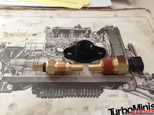
I took a picture to show the difference, the one on the right is from the GM one Autosportlabs site, and will wire straight into the MJ, the left is the early classic mini one.
Could you post up the 0-256 Degrees vs voltage chart please for the GM one ?
Thanks
David
Edited by Brocky on 31st May, 2013.
BTW - I took my buddy VTEC Pete out for a spin this weekend, and even though I am running her in, he gave it a name, the "Brocket"...cause I'm a brocket maaannn, nah nah nah nah nah nah nah nah nah nah nah....
Build thread - http://www.turbominis.co.uk/forums/index.php?p=vt&tid=7483
Katy Mini Owners Club Thread - http://www.turbominis.co.uk/forums/index.php?p=vt&tid=505552
Let's make sure you embarrass at least one VTEC MINI today !
https://www.facebook.com/groups/17557298589...096464253807802
|
KLAS
89 Posts
Member #: 2380
Advanced Member
Hamburg, Germany
|
|
the threads per inch doesn't matter. basicly you remove the threads of the GM sensor and then you have the right diameter to cut the 5/8 thread.
i don't have a chart, just used them with megasquirt so i didn't had to play around with the calibration when i started years ago
|
Brocky
809 Posts
Member #: 224
Post Whore
Katy TEXAS
|
|
Thanks,
So do you seal with a copper washer under the hex, as obviously the taper is removed ?
Cheers
Brocky
Edited by Brocky on 31st May, 2013.
BTW - I took my buddy VTEC Pete out for a spin this weekend, and even though I am running her in, he gave it a name, the "Brocket"...cause I'm a brocket maaannn, nah nah nah nah nah nah nah nah nah nah nah....
Build thread - http://www.turbominis.co.uk/forums/index.php?p=vt&tid=7483
Katy Mini Owners Club Thread - http://www.turbominis.co.uk/forums/index.php?p=vt&tid=505552
Let's make sure you embarrass at least one VTEC MINI today !
https://www.facebook.com/groups/17557298589...096464253807802
|
KLAS
89 Posts
Member #: 2380
Advanced Member
Hamburg, Germany
|
|
no, liquid thread sealer or teflon tape, whatever i find first
|
Rod S
5988 Posts
Member #: 2024
Formally Retired
Rural Suffolk
|
|
For the GM sensor, see here
http://www.diyautotune.com/catalog/gm-clos...ctor-p-115.html
(at the bottom of the description)
Resistance is quoted, not voltage because (as Tom pointed out earlier) they don't provide the volatge - they are biased with 5V through a fixed value resistor inside the ECU box and the combination of one fixed, one varying, gives the voltage signal at the mid point. You can't work that out unless you know the bias resistor value so I would be very surprised if MJ was asking you to enter voltages....
Only three points are quoted, that's because Megasquirt (and all other ECUs I've played with) only need three values. The sensor element inside all ECU compatible sensors is a Negative Temperature Co-efficient element that obeys a nice complex mathmatical equation such that given any three values everything else above, below and inbetween can be worked out. This is usually done by the tuning software (you won't even realise it's doing it) then loaded into the ECUs memory.
If MegaJolt requires more than 3 points then go to the Megasquirt-Extra forums and search for Steinhart-Hart.
That's the name of the equation and somewhere on the site is a spreadsheet that you can download, enter the 3 known points and get all the rest. Ignore the bit on the spreadsheet about bias resistor and generating the inc file, that's just for loading it into an MS CPU, just read from the second (resistance) and fourth (degrees C) or fifth (degrees F) columns. It's probably already setup with the GM data as that sensor is the usual choice for MS as well, but if not, just enter the 3 values from DIYAutotune in the yellow cells at the top of the sheet (you will probably have to convert to centigrade, the version of the spreadsheet on my PC, which came from the site a while ago, is centigrade only for data entry even though it calculates both centigrade and farenheight).
I used thread sealant (loctite) for my adapter and european sensor (again parallel threads after the mod) because my head face wasn't very flat there. They are usually spot faced at production (ie, milled nice and flat for a small circle around the hole), in which case a copper washer would work, but mine wasn't....
EDIT - typo and a bit of extra info.
Edited by Rod S on 1st Jun, 2013.
Schrödinger's cat - so which one am I ???
|
Brocky
809 Posts
Member #: 224
Post Whore
Katy TEXAS
|
|
Thanks for the info Rod,
Really appriciate your time, :)
The reason I mention voltage is because that is what the input says for the calibration here:
or I am I missing something ?
Cheers
Brocky
Edited by Brocky on 1st Jun, 2013.
BTW - I took my buddy VTEC Pete out for a spin this weekend, and even though I am running her in, he gave it a name, the "Brocket"...cause I'm a brocket maaannn, nah nah nah nah nah nah nah nah nah nah nah....
Build thread - http://www.turbominis.co.uk/forums/index.php?p=vt&tid=7483
Katy Mini Owners Club Thread - http://www.turbominis.co.uk/forums/index.php?p=vt&tid=505552
Let's make sure you embarrass at least one VTEC MINI today !
https://www.facebook.com/groups/17557298589...096464253807802
|
Rod S
5988 Posts
Member #: 2024
Formally Retired
Rural Suffolk
|
|
Well,
First I have to say I've never used MJ so this is a bit of a surprise....
A bit like Wil said the other day, the ECU you choose is what suits you and what you are used to..... (and I'm used to MS).
From your link and a very quick scan of the Autosports website it appears there isn't a dedicated temperature input but simply 0-5V inputs you can use as temperature.
PLEASE, anyone familiar with MJ tell me now if I'm wrong....
If they are just 0-5V inputs you can use as temperature, then yes, you need voltage, not resistance.
Here is a typical thread on their forum
http://www.autosportlabs.org/viewtopic.php...ure+input#19157
This implies you have to build your own bias resistor circuit - to create the 0-5V - and enter your own ADC values into the MJ rather than just entering 3 temperature/resistance values and letting the tuning software create the table....
What you must bear in mind, the ADC table simply is NOT linear for a temperature input, it is a curve, so the CPU needs many values - normally all these values (1024 of them) would be created by the software.....
I can't see all the table on the link but I guess it is a 1024 array (2^10) like MS so hopefully it will import from a spreadsheet (or you have a hell of a lot of typing to do...)
The bias resitor circuit is quite simple, lots of examples on the MS-Extra site or Jean's site (those of us using Jean's IOx on MS are quite used to this) you just need the 5V (Vref) output from the MJ and a couple of capacitors and a resistor to protect the input and you can create the 0-5V signal.
Then load the ADC table and you should have what you want.
The MS-Extra spreadsheet (email to follow) creates the ADC table once you enter the bias resistor value.
I'm surprised this is so complicated with MJ, but maybe it isn't and I just haven't looked closely enough.
Schrödinger's cat - so which one am I ???
|
Brocky
809 Posts
Member #: 224
Post Whore
Katy TEXAS
|
|
Thanks Rod,
I am in comunication with Brent now,
The number of lines for the curve is 256,
I'm checking just now if the later MJ's have the resistive circuit built in or not.
If not I will get the details on building one and post up here.
I will also see if I can use a mini sensor or not to save on the machining, and also post the curves need for each etc.
Cheers for the pointers, interesting I have been back and forth on email with brent for a week or so regarding sensor physical details etc,
Brocky
Edited by Brocky on 1st Jun, 2013.
BTW - I took my buddy VTEC Pete out for a spin this weekend, and even though I am running her in, he gave it a name, the "Brocket"...cause I'm a brocket maaannn, nah nah nah nah nah nah nah nah nah nah nah....
Build thread - http://www.turbominis.co.uk/forums/index.php?p=vt&tid=7483
Katy Mini Owners Club Thread - http://www.turbominis.co.uk/forums/index.php?p=vt&tid=505552
Let's make sure you embarrass at least one VTEC MINI today !
https://www.facebook.com/groups/17557298589...096464253807802
|
Brocky
809 Posts
Member #: 224
Post Whore
Katy TEXAS
|
|
Bingo,
By default the MJ uses the thermister type sensor for the aux input. 
But this still leaves me with out a curve 
BTW - I took my buddy VTEC Pete out for a spin this weekend, and even though I am running her in, he gave it a name, the "Brocket"...cause I'm a brocket maaannn, nah nah nah nah nah nah nah nah nah nah nah....
Build thread - http://www.turbominis.co.uk/forums/index.php?p=vt&tid=7483
Katy Mini Owners Club Thread - http://www.turbominis.co.uk/forums/index.php?p=vt&tid=505552
Let's make sure you embarrass at least one VTEC MINI today !
https://www.facebook.com/groups/17557298589...096464253807802
|
Rod S
5988 Posts
Member #: 2024
Formally Retired
Rural Suffolk
|
|
Brocky, posts crossed, I've just emailed you the spreadsheet to calculate all 1204 voltage points on the curve...
You should be able to pick what you want out of that....
Schrödinger's cat - so which one am I ???
|
Rod S
5988 Posts
Member #: 2024
Formally Retired
Rural Suffolk
|
|
MS uses 1024 points, 2^10 so it seems MJ uses 2^8 if you only need 256 points.
No big deal, back to Wil's comment, it's what you're used to and happy with.
Edited by Rod S on 1st Jun, 2013.
Schrödinger's cat - so which one am I ???
|
Brocky
809 Posts
Member #: 224
Post Whore
Katy TEXAS
|
|
Thanks Rod,
So basically, the V4 MJ has build in dedicated circuit for the GM Thermister type sensor, v3 and earlier need the resistor circuit. I think I have the V4 which is a smaller unit, although I did buy it in June 2010, I will check to make sure.
I am happy with what I have since I run a carb set up, I does and will do what I need it to, and for 100 quid (160 bucks) that I paid for it I am more than happy plus I can just keep adding...as there are still lots of functionality that I havent played with yet,
I think it is great that I can set it up as a variable fan switch since it can trigger an output base on a varible input thresthold, so I can have a second fan come on sooner or later than the stock fan switch, and all I need is a relay, as it only puts out 500mA, but much is much cheaper than a varible fan switch, and less complicated in terms of hardware and wiring.
Neat really. the rev counter wired straight up as well.
Some one else mentioned this earlier, and I am also wondering if there is a smart way to link the lambda output to the jolt input and use an output to back off the boost or timing or similar??? (I have innovative motorsport set up for AFR) or possibly control staged boost in the higher gears buy opening a solenoid etc.
I have even thought about having a little servo on the carb mixture screw, that adjusts on lambda output, but not sure what the response operator would look like? I think a knock sensor would go along way to, but I am sure this has already been discussed at length, for the 5 port.
Edited by Brocky on 1st Jun, 2013.
BTW - I took my buddy VTEC Pete out for a spin this weekend, and even though I am running her in, he gave it a name, the "Brocket"...cause I'm a brocket maaannn, nah nah nah nah nah nah nah nah nah nah nah....
Build thread - http://www.turbominis.co.uk/forums/index.php?p=vt&tid=7483
Katy Mini Owners Club Thread - http://www.turbominis.co.uk/forums/index.php?p=vt&tid=505552
Let's make sure you embarrass at least one VTEC MINI today !
https://www.facebook.com/groups/17557298589...096464253807802
|
|
Home > Help Needed / General Tech Chat > Megajolt Variable input - OEM mini temp sender
|
|
Users viewing this thread:
none. (+ 1 Guests)
|
|
|
