Donations towards server fund so far this month.

 
£0.00 / £100.00 per month
Page:
Home > A-Series EFI / Injection > Wideband placement

TMan

3 Posts
Member #: 11662
Junior Member

Hi all,

First post, been following this forum for a number of years now. Loads of great info, thanks *smiley*

Im collecting parts to implement sequential EFI using MS3, and i wondering about placement of wideband sensors in the exhaust manifold. This is currently for a NA engine, my final aim being forced induction. For the time being i just want to learn about EFI.

I want to install two widebands to enable accurate tuning of AFR, however after reading on here the only examples i can find (by paul and rod) are using sample chambers. Is this a must for monitoring both inner and outer? Im wondering if this was just necessary for turbocharged engines?

At the risk asking a completely idiotic question, can i place the widebands close to the cylinder head before the pipes merge? Im currently running a minispares LCB.

Also, wondering if anyone has used these controllers: https://ldperformance.co.uk/product/wideband-controller/

Cheers. T


jbelanger

1267 Posts
Member #: 831
Post Whore

Montreal, Canada

You don't need sample chambers on an NA engine. They are used to avoid exposing the sensor to the high pressure upstream of the turbo while still sampling the exhaust gas at that point.

Also, make sure that the sensors are not too close to the head because that would expose them to too much heat. Follow the recommendation of your chosen wideband controller. I'm not sure an LCB will allow this. Using heat sinks might work but using a controller that allows you to monitor the sensor temperature would still be a good idea.

Jean

http://www.jbperf.com/


Rod S

User Avatar

5988 Posts
Member #: 2024
Formally Retired

Rural Suffolk

As Jean says, the sample chamber concept is to put the sensors in the same pressure and temperature environment as they would see on a NA engine. Particularly pressure - excess heat before a turbo will shorten their lives but the continually varying pressure will mean they will not be accurate (look at the datasheets for the sensors themselves and you will see how the output varies with pressure so, unless the controller can also read pressure at the sensor location and compensate, the reading will never be right).

re. the "new" ADV sensors (and associated controllers), I first read about them a couple of years ago and opinions were very mixed back then. I've never followed it up but the "standard" 4.2 and 4.9 sensors are relatively cheap now (as well as a lot of good makes of controller) so I have no desire to try anything "new".
I use the 14point7 controllers (with 4.2 or 4.9 sensors), one of his range that monitors temperature.

Schrödinger's cat - so which one am I ???


TMan

3 Posts
Member #: 11662
Junior Member

Thanks for the feedback gents.

In terms of heatsink, the only 'off the shelf' item i can really find is the innovate HBX-1. Bit of googling shows other people have just made their own heat-shield from copper plate. The HBX-1 seems a bit pricey if a home made copper shield does the job.

Any suggestions/experiences?

Cheers

T


jbelanger

1267 Posts
Member #: 831
Post Whore

Montreal, Canada

I don't have experience with heat sinks or even reliable second hand information. The main issue is that people are happy if they don't get an error code from their controller or go through sensors quickly. That doesn't mean they have solved their overheating issues.

I assume you can use a home made solution successfully but I'll come back to my previous recommendation of using a controller that gives you sensor temperature information. This is the only way you'll know that you have a safe setup.

http://www.jbperf.com/


Paul S

User Avatar

8604 Posts
Member #: 573
Formerly Axel

Podland

No need for a heat sink if you install the sensors the recommended distance from the head.

If you put them on the 2 down legs of the LCB, just above the diff, they will be fine. Well, that's how I've always done it without issue.

Saul Bellow - "A great deal of intelligence can be invested in ignorance when the need for illusion is deep."
Stephen Hawking - "The greatest enemy of knowledge is not ignorance, it is the illusion of knowledge."


TMan

3 Posts
Member #: 11662
Junior Member

Thanks jbelanger, ill keep that in mind when choosing a controller. At the moment i haven't found one with that functionality within my budget. Theres some cheap and cheerful EGT gauges + k-type sensors on eBay, i know that won't give me the lambda sensor temp but at least ill have an idea?

paul, thanks. thats where i was thinking of placing them. Did you use angled bosses to keep the sensor tip facing downwards?

Cheers

T


Rod S

User Avatar

5988 Posts
Member #: 2024
Formally Retired

Rural Suffolk

As Paul says, the position you are thinking of shouldn't be a problem on a N/A engine.
For my initial N/A tests I used the standard A-Plus manifold (two long mild steel pipes after the cast bit) with the LSUs about 2/3 the way down. No long term testing but nothing to suggest it wasn't OK, it met the criteria for most of the wideband contollers distance recommendations. Bosses were at 90 degrees which was again fine by the controllers recommendations.
I wouldn't bother with EGT type sensors yet, just think about what you are doing long term, esp. if going MS3 (or even MS2 like I use) as there are lots of possibilities for controllers that interface specifically with the MS hardware or Jean's IOx range (which also integrates with the MS2/3) like I use.

Schrödinger's cat - so which one am I ???


Paul S

User Avatar

8604 Posts
Member #: 573
Formerly Axel

Podland

Same as Rod but did many thousands of miles testing the Siamese code. Only one sensor failure but I don't think it was anything to do with the placement, just dumb user :)

Saul Bellow - "A great deal of intelligence can be invested in ignorance when the need for illusion is deep."
Stephen Hawking - "The greatest enemy of knowledge is not ignorance, it is the illusion of knowledge."


johntrhodes81

16 Posts
Member #: 11718
Member

On a turbo mini are people just putting of O2 sensors between the exhaust ports and the turbo? There are posts from the 2009 era that talk about sample chambers but I have not seen posts about that since.

The picture of the sample chambers are gone too, is it basically a small tube bypassing the turbo to direct exhaust on a O2 sensor? I am not seeing information on how to build it. How small of a tube can be used to and from the sample chamber itself?

Thanks,
John


stevieturbo

3569 Posts
Member #: 655
Post Whore

Northern Ireland

widebands do not like excess heat or pressure.

Hence when trying to monitor for charge robbing and sampling all of the exhaust ports, sampling chambers are needed to create a cooler environment, and without the pressure.
Although Bosch do now have sensors for pre-turbo use, I'd imagine they're a clean fortune though and would require their own dedicated controller.

9.85 @ 145mph
202mph standing mile
speed didn't kill me, but taxation probably will


johntrhodes81

16 Posts
Member #: 11718
Member

stevieturbo,
Yes the sensors are $200 each with a $4000 controller. I will leave that to race teams. Thanks. So for a sampling chamber, would a 50 mm section of 50 mm pipe to hold the sensor with 10 mm tube from the manifold to the chamber and more 10 mm tube to the downpipe work? While 10 mm copper tube would be easy, cheap and would dissipate heat, it would likely melt right?

I assume a heat sink bung:
https://www.aemelectronics.com/products/sen...-o2-sensor-bung

And a heat sink bung extender wouldn't be enough since the pressure is still an issue?
https://www.innovatemotorsports.com/heat-si...nder-hbx-1.html

Thanks,
John

Edited by johntrhodes81 on 2nd Oct, 2022.


stevieturbo

3569 Posts
Member #: 655
Post Whore

Northern Ireland

Heat sinks alone will be no use due to pressure.

I would see no reason for a pipe as large as 10mm.

And remember, as you wish the sensor to be on a low/no pressure area, the pipe discharging exhaust gasses would need to be larger than that feeding the sensor.
And on a turbo setup, remember that this is effectively a leak pre-turbo, so you'd want to keep that as low as you can.

But are you doing an injection system where you even need to monitor all ports ?

9.85 @ 145mph
202mph standing mile
speed didn't kill me, but taxation probably will


johntrhodes81

16 Posts
Member #: 11718
Member

stevieturbo,

Ok 3 mm or 5 mm supply and 10 mm return? 1 WBO2 on an "outer" cylinder & 1 on an "inner" cylinder so as to ensure no port robbing. Is copper tube crazy for this in your opinion?

Thanks,
John

Edited by johntrhodes81 on 2nd Oct, 2022.


Graham T

User Avatar

604 Posts
Member #: 1106
Post Whore

Hungerford, Berks

On 2nd Oct, 2022 johntrhodes81 said:
On a turbo mini are people just putting of O2 sensors between the exhaust ports and the turbo? There are posts from the 2009 era that talk about sample chambers but I have not seen posts about that since.

The picture of the sample chambers are gone too, is it basically a small tube bypassing the turbo to direct exhaust on a O2 sensor? I am not seeing information on how to build it. How small of a tube can be used to and from the sample chamber itself?

Thanks,
John


If this helps,

I feed the sample chambers with 6mm OD x 1mm walled ST/ST
The chambers are 16mm ID and the pipe from the chamber to the downpipe is 16mm OD x 1mm


Here are my original sample tubes/ Chambers for the LSU’s.


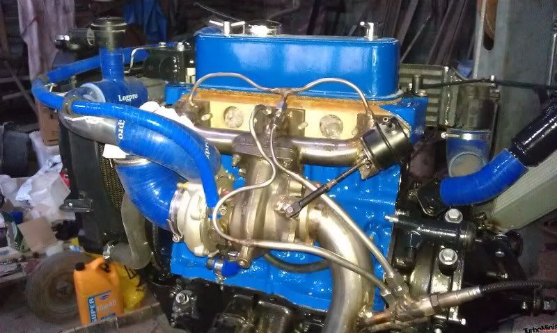
A little bit of discussion here:
http://www.turbominis.co.uk/forums/index.php?p=vt&tid=572407

(specifically regarding the transition of the feed pipes from 6mm to 8mm OD)


Once I changed to a “remote” Turbo:


From a few posts into this page:
http://www.turbominis.co.uk/forums/index.p...d=611675&fr=100


Edited by Graham T on 3rd Oct, 2022.

’77 Clubman build thread
http://www.turbominis.co.uk/forums/index.php?p=vt&tid=618189

Siamese 5 port EFI testing
http://www.turbominis.co.uk/forums/index.php?p=vt&tid=611675


johntrhodes81

16 Posts
Member #: 11718
Member

Thanks much!

Home > A-Series EFI / Injection > Wideband placement
Users viewing this thread: none. (+ 1 Guests)  
To post messages you must be logged in!
Username: Password:
Page: