|
Home > A-Series EFI / Injection > EFI Testing - Dyno Day 6: 1.5:1 Ratio rockers
|
Graham T

604 Posts
Member #: 1106
Post Whore
Hungerford, Berks
|
|
On 8th Jan, 2018 robert said:
it does look like with a bit of jiggery pokery it will match the innovate most of the time .
Yes Robert, I think there is a little bit more testing to be done with the MAP Sample angle and window to see if I can make the MAP signal more aligned to the innovate, or even just the Iox Pressure measurements.
However, I am hoping by putting the fuel filter in line, it might eliminate some of the irregularities before I continue playing with the Map sampling settings any more.
Also, as this is all Carb data and Im going to be swapping back to Injection imminently, Id assume with a different inlet design, larger plenum and longer runners, the dynamics would be totally different and so there is no real advantage to getting these settings right for the carb setup.
On 8th Jan, 2018 Paul S said:
A decent buffer on the signal line should sort it out.
Here's on old plot from a simulation showing the variation of pressure in the inlet runner:
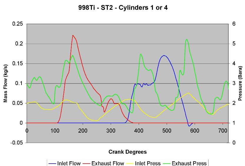
The peaks of the pulses ocurr at different times in the cycle depending on the engine speed. The pulses move at the speed of sound and are not synched to engine speed. So with your map sampling you will be picking up the MAP during the intake event, but it will not be the same as the cycle average.
Thanks Paul, I think that pretty much confirms what is said in the MS3 Manuals with regard MAP sampling, (but with more information).
Id like to have the MS2 MAP smoother and more a true representation of the average cycle, so I think I will need to revisit all this once I have the new Manifold designed built and bolted on.
77 Clubman build thread
http://www.turbominis.co.uk/forums/index.php?p=vt&tid=618189
Siamese 5 port EFI testing
http://www.turbominis.co.uk/forums/index.php?p=vt&tid=611675
|
Graham T
604 Posts
Member #: 1106
Post Whore
Hungerford, Berks
|
|
Before I go and pull the Engine bay apart yet again to remove the Carb and start on a new Injection manifold, I thought I would just do a couple more tests with the Pressure signals, just so that I have fair comparison with the different future inlet design.
All the below tests were with a fuel filter and 0.6mm MIG tip in the MAP signal line, feeding both the MS2 MAP sensor and Iox pressure sensor.
To start with the MAP Sample Angle was at its default of 90Deg and the MAP Sample window was at its default of 10Deg.
Happy Days!!


Compared to the previous, without fuel filter in the MAP signal line:

But just to see the effects, if any, on changing the MAP Sample settings with the Pressure signal damper in place:
MAP Sample Angle changed from 90Deg BTDC to 45Deg BTDC

And then leaving the MAP Sample Angle at 45Deg BTDC, but also increasing the MAP Sample window from 10Deg to 45Deg.

Looking at the Post IC trace, it appears Im going to need a few more fuel filters.
I think I will leave the MAP sample settings at their defaults for now and I can pursue this further once I have the new manifold on the car.
Last job before I pull it all apart is going to be to check for leaks between the IC and the Plenum to see whether the difference between Post IC pressure and manifold pressure is actually just a leak or is actually a pressure drop through the Metro turbo plenum and carb assembly.
Edit - added line at beginning WRT fuel filter.
Edited by Graham T on 14th Jan, 2018.
77 Clubman build thread
http://www.turbominis.co.uk/forums/index.php?p=vt&tid=618189
Siamese 5 port EFI testing
http://www.turbominis.co.uk/forums/index.php?p=vt&tid=611675
|
Rod S
 (2)[/url] by [url=https://www.flickr.com/photos/150672766@N03/]Rod Sugden[/url], on Fli)
5988 Posts
Member #: 2024
Formally Retired
Rural Suffolk
|
|
On 13th Jan, 2018 Graham T said:
Last job before I pull it all apart is going to be to check for leaks between the IC and the Plenum to see whether the difference between Post IC pressure and manifold pressure is actually just a leak or is actually a pressure drop through the Metro turbo plenum and carb assembly.
Well,On 13th Jan, 2018 Graham T said:
or is actually a pressure drop through the Metro turbo plenum and carb assembly. my first guess would be yes, because that's how an SU carb works.
Probably even more so with the turbo variant with its inlet restrictor plate.
The SU is a very crude device, the way it was modified to suit forced injection is also quite basic. Nothing against that basic concept but it's not going to make definitive pressure readings around the cycle as easy as EFI.
Schrödinger's cat - so which one am I ???
|
robert

6743 Posts
Member #: 828
Post Whore
uranus
|
|
so that huge change is smoothness and accuracy compared to the previous traces was done with the same 10d and 90 d defualt ,and it was all down to the use of a fuel filter in the line ?
Medusa + injection = too much torque for the dyno ..https://youtu.be/qg5o0_tJxYM
|
Graham T
604 Posts
Member #: 1106
Post Whore
Hungerford, Berks
|
|
Yes Robert,
The only change I made for the first test was to add the fuel filter, with a MIG tip in it, with MAP sample settings default at 10deg and 90deg.
I had missed a line in my above post which I have now edited to clarify.
77 Clubman build thread
http://www.turbominis.co.uk/forums/index.php?p=vt&tid=618189
Siamese 5 port EFI testing
http://www.turbominis.co.uk/forums/index.php?p=vt&tid=611675
|
Rod S
5988 Posts
Member #: 2024
Formally Retired
Rural Suffolk
|
|
Two further thoughts.
If damping the signal has had such an effect, is the un-damped response simply down to the physical size of the standard turbo SU inlet manifold ?
I don't know where the ideal point to start measuring it is (throttle plate or somewhere further back in the system) but it must be tiny in comparison the the 1293cc of the engine.
On an injection setup someone on here in the early days (I can't remember who it was nor can I find the thread/posts on the subject) did a lot of research and came up with a figure, IIRC, of between 1 and 1.5X engine capacity being the ideal volume. Whatever the figures quoted at the time actually were, I ended up making mine 1.3X. That in itself must provide a lot of damping, a similar analogy to the length/diameter of the hose to Robert's setup (plus long tubes with relatively small diameters add further damping from wall friction effects).
Secondly, back to injection, any form of damping could change the response of AE.
Depending how much you have it biased between TPS dot and MAP dot, the MAP dot element will presumably become less effective.
Schrödinger's cat - so which one am I ???
|
Graham T
604 Posts
Member #: 1106
Post Whore
Hungerford, Berks
|
|
On 14th Jan, 2018 Rod S said:
Two further thoughts.
If damping the signal has had such an effect, is the un-damped response simply down to the physical size of the standard turbo SU inlet manifold ?
Dont forget the EFI data both using the MPI Manifold and my original angled injector design, showed exactly the same trend with MAP.
Hence the reason I thought it would be good to do the trials whilst I had the Carb still bolted on - so that I have something to compare between carb, MPI Inlet manifold and whatever my New plenum shape and volume will be.
I estimated the MPI Plenum at 620cc and the Plenum volume of my original Angled injector setup (used for the SRE Dyno session back in 2015) at 600cc.
On 14th Jan, 2018 Rod S said:
I don't know where the ideal point to start measuring it is (throttle plate or somewhere further back in the system) but it must be tiny in comparison the the 1293cc of the engine.
I can get some bascic volume measurements for the Metro Turbo Inlet manifold a bit later.
On 14th Jan, 2018 Rod S said:
On an injection setup someone on here in the early days (I can't remember who it was nor can I find the thread/posts on the subject) did a lot of research and came up with a figure, IIRC, of between 1 and 1.5X engine capacity being the ideal volume. Whatever the figures quoted at the time actually were, I ended up making mine 1.3X. That in itself must provide a lot of damping, a similar analogy to the length/diameter of the hose to Robert's setup (plus long tubes with relatively small diameters add further damping from wall friction effects).
I know with my current inlet manifolds, the plenums are too small.
At this point, Ive worked out that I think I have enough room for a 2200cc plenum. I am still working on it and might be able to increase that slightly.
My plan is to have at least one end removable on a cylindrical plenum, then have a stud welded internally on each end plate, to which I can mount some solid discs in order to alter the plenum volume as and If necessary.
Bad Idea?
On 14th Jan, 2018 Rod S said:
Secondly, back to injection, any form of damping could change the response of AE.
Depending how much you have it biased between TPS dot and MAP dot, the MAP dot element will presumably become less effective.
Apparently it is set up at 100% TPS, hence I imagine that MAP signal dampening will not affect the AE at this point.
77 Clubman build thread
http://www.turbominis.co.uk/forums/index.php?p=vt&tid=618189
Siamese 5 port EFI testing
http://www.turbominis.co.uk/forums/index.php?p=vt&tid=611675
|
Paul S
8604 Posts
Member #: 573
Formerly Axel
Podland
|
|
Plenum volume has little impact, other than it will dampen the pulses for the MAP signal. I seem to remember working to 1.5 times engine capacity.
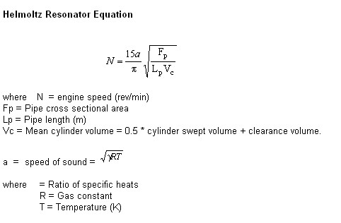
Helmholtz is your friend:
Runner length and diameter is what determines the pulse, diameter has the most impact on the amplitude whereas runner length determines the timing.
Look how my plot above times the inlet pressure higher than the exhaust at valve overlap, the main factor in achieving high VE.
Saul Bellow - "A great deal of intelligence can be invested in ignorance when the need for illusion is deep."
Stephen Hawking - "The greatest enemy of knowledge is not ignorance, it is the illusion of knowledge."
|
Graham T
604 Posts
Member #: 1106
Post Whore
Hungerford, Berks
|
|
Thanks Paul.
I've been reading up on as much as possible with regard to runner tuning for a while now, and to be fair most of it is a little above me.
There are so many opinions and theories on the interweb, it all gets a bit confusing.
Question on that Equation:
why is Speed of sound multiplied by 15?
77 Clubman build thread
http://www.turbominis.co.uk/forums/index.php?p=vt&tid=618189
Siamese 5 port EFI testing
http://www.turbominis.co.uk/forums/index.php?p=vt&tid=611675
|
Paul S
8604 Posts
Member #: 573
Formerly Axel
Podland
|
|
I think that in that instance it's just a conversion constant. Depends on the units.
A bit more here from my textbook:
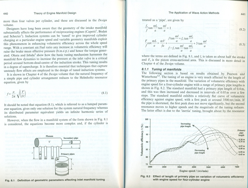
Saul Bellow - "A great deal of intelligence can be invested in ignorance when the need for illusion is deep."
Stephen Hawking - "The greatest enemy of knowledge is not ignorance, it is the illusion of knowledge."
|
Graham T
604 Posts
Member #: 1106
Post Whore
Hungerford, Berks
|
|
Greetings.
Just a bit of an update on the progress of my latest (read 7th) experimental manifold design X7
This has been a somewhat mammoth job so far to try to create something that fits in the space I have and to try to satisfy all the criteria I had:
1) Staged injection Get 4 injectors installed in a way that I felt was going to give the least complication with setup
2) Runner lengths deciding on/ Calculating a suitable length which would actually fit.
3) Plenum volume Increase the volume considerably from the ~600cc
4) Get the best flow possible.
As far as fitting the 4 injectors in, this has been my biggest issue from the beginning.
The original Angled injector manifold seemed to bias the fuelling to either inner or out cylinders, depending on which injector boss the primary injector was installed in.
Ultimately the best setup I achieved to date was using the MPI manifold, but that was limiting due to only having the 1 injector per port.
So in order to utilise the MPI Inlet manifold settings I already have, I have based the positioning and angle of the primary injector on the MPI Manifold,
The secondary injectors are then slotted in behind and as close as possible to the primary injector.
I have also decrease the angle of the secondary injector off of the horizontal plane of the runner in order to aim the stream at the same point as the primary stream in the head port. Im not even sure if that is necessary but it felt like the right thing to do.
Again, to replicate the MPI ports as much as possible, I have made the Injector section of the manifold a straight shot into the Head port, with a length of 110mm and internal diameter of ~32mm, as close as I could get to the MPI and the Metro Turbo Carb Manifold runner diameters.
So the Injector section of the Inlet manifold is like this:


(Ignore the extra pipes coming from the fuel rail. These were from a previous experiment)


Hopefully this will prove to be successful and I will be able to use the injection timing figures for the primary injectors that I have had success with over the last year.
If so and if I can get the staged injector timing configured successfully, then this will be the final time I will need to change anything relating to the injector positioning, meaning that at least I have a constant regardless of the runner length/ angle/ shape or plenum designs up stream.
Edited by Graham T on 27th Mar, 2018.
77 Clubman build thread
http://www.turbominis.co.uk/forums/index.php?p=vt&tid=618189
Siamese 5 port EFI testing
http://www.turbominis.co.uk/forums/index.php?p=vt&tid=611675
|
Graham T
604 Posts
Member #: 1106
Post Whore
Hungerford, Berks
|
|
Next was working out the runner lengths and get an idea of the plenum dimensions in order to fit it all under the bonnet.
I took a bit more of a look at the Helmholtz resonator equation and also did a load of searching on the interweb and finally came up with a runner Length which I felt was around where I wanted to start off.
Of course this might need revisiting, but for now its a start point
Without any CAD software it was back to basics on the drawing board, measuring the space available under bonnet to create a drawing I could use to position card cut outs of the component pieces.

So after lots of jiggling of the cardboard cut-outs, changing shapes, lengths, etc. I got what I thought was the best compromise and tacked up the aluminium for test fitting.

Lots of tweaking later I had it fitting reasonably well and so it was on to making flanges for the extended runners and welded it all up.


Edited by Graham T on 27th Mar, 2018.
77 Clubman build thread
http://www.turbominis.co.uk/forums/index.php?p=vt&tid=618189
Siamese 5 port EFI testing
http://www.turbominis.co.uk/forums/index.php?p=vt&tid=611675
|
Graham T
604 Posts
Member #: 1106
Post Whore
Hungerford, Berks
|
|
With the runners complete, the next was the Plenum design.
The first part was creating the flanges to connect to the extended runners, so that I could get the basic Plenum barrel in place on the car.


Apparently this was the simple part complete!
When I was up with Robert at the Last Dyno Session in December 2017, we started discussing a new manifold design for the staged injection and came up with a few ideas which might help to increase plenum volume whilst being able to fit it all in, as well as help to improve flow.
Hence when it came to this stage of the build I engaged Roberts services once more to guide me through and assist with the design.
Before constructing it out of Aluminium, I created a card mock-up of the plenum to make sure that it fitted in the limited space.


Onto the next step of making it:


And the Manifold so far:


Edited by Graham T on 27th Mar, 2018.
77 Clubman build thread
http://www.turbominis.co.uk/forums/index.php?p=vt&tid=618189
Siamese 5 port EFI testing
http://www.turbominis.co.uk/forums/index.php?p=vt&tid=611675
|
Graham T
604 Posts
Member #: 1106
Post Whore
Hungerford, Berks
|
|
At this point there is still a fair amount to do:
signal ports to add
IACV tapping to add
Fill all pin holes
Make up supports for the front of the Plenum
sort the aesthetics.
Move turbo coolant and heater pipes
Rewire as necessary
The Manifold has been pressured tested up to 25 PSI at the moment, but still have a few more pin holes to sort out which can be seen when pressurising it submerged in water.
My TIG skills are still developing, so every time I fill one hole, it appears I make 2 more, hence I have been chasing the holes around for the last 10 days.
Although there is obviously more work to be done, this point in the build seemed the right time to take it for some flow testing to see how it performs.
I took 4 Manifolds with me to get flow tested so that I had some comparative data:
The Metro Turbo Carb setup
Standard MPI Manifold with Throttle body and pipework
New X7 Inlet manifold with TB
Original Angled Injector manifold.
We flow tested tested 3 of the 4 manifolds and got the following results:
The Metro Turbo Carb setup
125 CFM @ 28 inH2O
MPI manifold
194 CFM @ 28 inH2O
X7 Inlet Manifold
240 CFM @ 28 inH2O
So it flows pretty well, which is great, but there does appear to be some biasing toward no 1/2 cylinder port.
We have a plan in place to try to rectify this problem and hopefully by the end of the Coming weekend, I should have a fairly complete Inlet manifold, flowing well with no Biasing.
Then it is a case of finishing off the other associated changes so that I can get the car back on the road for more testing.
The Actual volume of the plenum has gone just a little over my targeted 2 x Engine capacity
A rather large 2.9 Litres.
Edited by Graham T on 27th Mar, 2018.
77 Clubman build thread
http://www.turbominis.co.uk/forums/index.php?p=vt&tid=618189
Siamese 5 port EFI testing
http://www.turbominis.co.uk/forums/index.php?p=vt&tid=611675
|
minimole23
4300 Posts
Member #: 1321
Post Whore
Wiltshire
|
|
Wow, that plenum is like a scupture. Excellent work.
On 7th Oct, 2010 5haneJ said:
yeah I gave it all a good prodding
|
stevieturbo
3569 Posts
Member #: 655
Post Whore
Northern Ireland
|
|
That's a hell of a lot of plenum volume to have on such a small engine....behind the throttle blade.
9.85 @ 145mph
202mph standing mile
speed didn't kill me, but taxation probably will
|
Graham T
604 Posts
Member #: 1106
Post Whore
Hungerford, Berks
|
|
On 27th Mar, 2018 minimole23 said:
Wow, that plenum is like a scupture. Excellent work.
Thanks,
It was looking fairly reasonable 10 or 11 days back when those photos were taken, but now I have been attacking it trying to block up all the holes, its not looking quite as good as it was
Hence alot of clean up to do.
On 27th Mar, 2018 stevieturbo said:
That's a hell of a lot of plenum volume to have on such a small engine....behind the throttle blade.
Yeah, its just a little larger volume than I had worked it out to be originally, but I had to make a few changes from the original design to get it to fit.
I'll see how it is when I have it drivable, I can always reduce the volume if needed - I think.
77 Clubman build thread
http://www.turbominis.co.uk/forums/index.php?p=vt&tid=618189
Siamese 5 port EFI testing
http://www.turbominis.co.uk/forums/index.php?p=vt&tid=611675
|
Graham T
604 Posts
Member #: 1106
Post Whore
Hungerford, Berks
|
|
As previously mentioned, during the first Flow bench session with the new manifold there was a detectable difference in flow between the 2 runners, but we had no measurable way to confirm the amount of biasing that was evident from the cotton thread, which was held in the air flow at the exit of the inlet runners.
However, the theory was that the shape of the plenum directly after the elbow to the throttle body, could have been biasing flow back toward the runner for cylinders 1 /2.

The fix Robert suggested to was to test reshaping of the plenum and measuring the pressures at the inlet runner exits, rather than relying on the cotton thread in the air flow.

So after cutting the side out of the plenum in the area indicated above and making up some card sections to tape in place, I bought a cheap Ebay Manometer and took the assembly back for more testing.
The first test was increasing the width of the plenum at the arrows in the below by 16mm, creating a smooth shallow convex arc

As shown in the below tables, this proved a little too much and actually started biasing to the runner for Cylinders 3 / 4
The next test was with a slightly less width increase of 12mm, creating a fairly straight side wall, though still very slightly convex.
Ultimately this configuration seems to balance the ports fairly well.
For testing, one tube of the Manometer was held just inside of the Runner exit at 9 positions. The other Manometer tube was positioned as far outside of the air flow as possible and the manometer was set to mBar.


So the reshaping of the Plenum appears to have fairly well fixed the biasing.
Something that was forgotten was to tape a bit of card back onto the Manifold replicating the original concave curve, to get comparable measurements of the issue that was first noticed with the cotton thread, but it is now a bit late.

Additionally from the test results it is also possible to see that the bottom of the runner exit is flowing more than the top. Possibly due to the curve of the actual runner further back?
Finally, I also took the Intercooler with me for flow testing.
In order to route the pipework to the new Plenum I had to change the Intercooler Exit.

Feeding the Intercooler via its inlet the flow rate was 183 CFM @ 28 inH20
Reversing the air flow though the intercooler, so feeding air in through the exit pipe the flow rate was 185 CFM @ 28 inH20.
In Hindsight, I should have tried to get into the end tank on the exit side to try to radius it out a little into the new pipe
Edited by Graham T on 2nd Apr, 2018.
77 Clubman build thread
http://www.turbominis.co.uk/forums/index.php?p=vt&tid=618189
Siamese 5 port EFI testing
http://www.turbominis.co.uk/forums/index.php?p=vt&tid=611675
|
Rod S
5988 Posts
Member #: 2024
Formally Retired
Rural Suffolk
|
|
Although it would be quite tricky to implement on something so small, back in my days working on the old gas cooled magnox reactors, what we had inside all the 90 degree elbows was a series of curved guide vanes. They were specifically there as "flow straighteners" to ensure uniform gas entry to the boilers, circulators etc.
I've also seen similar in HVAC ducting, as per Google https://www.google.co.uk/search?q=guide+van...iw=1396&bih=668
Also, with your throttle spindle being "horizontal" (ie, across the radius of the bend), did you do any measurements at part throttle ?
The different distances of the top and bottom the throttle plate to the bend may also have an effect when it's not fully open.
Schrödinger's cat - so which one am I ???
|
Paul S
8604 Posts
Member #: 573
Formerly Axel
Podland
|
|
I would think long and hard about what your tests are telling you before you worry unduly about apparent biasing.
You've measured the plenum air flow at 240 CFM, actual air flow will be about half that under boost due to the pressure/density. Therefore velocity will be much lower and any kinetic energy impacts will be much lower.
Did you measure each runner at a time, or both at once? If you did both at once, then the flow through the inlet will be twice as much again as you would see in practice.
Saul Bellow - "A great deal of intelligence can be invested in ignorance when the need for illusion is deep."
Stephen Hawking - "The greatest enemy of knowledge is not ignorance, it is the illusion of knowledge."
|
Graham T
604 Posts
Member #: 1106
Post Whore
Hungerford, Berks
|
|
Rod,
We had discussed using some form of guide vane as an option but as you point out, that seemed to me rather tricky to implement.
We also discussed the throttle body alignment with the curve. I would estimate it is around 22 deg off the horizontal.
But I had to dismiss any ideas of adjusting the throttle body orientation due to packaging. There was just no way to alter its angle within the space available.
Ultimately we never took any measurements with different Throttle body orientations nor at part throttle.
Ideally I would have liked the Throttle body straight into the plenum with the pipe bend back to the plenum outlet up stream of the throttle body, but again packaging made that almost impossible without a complete rethink on the air filter, MAF sensors and associated pipe work back to the turbo inlet.
Paul, the flow tests were carried out with both runners at once.
As this is all experimental, we will see how it all works in the real world and then I can go from there with adjustments if necessary.
77 Clubman build thread
http://www.turbominis.co.uk/forums/index.php?p=vt&tid=618189
Siamese 5 port EFI testing
http://www.turbominis.co.uk/forums/index.php?p=vt&tid=611675
|
Graham T
604 Posts
Member #: 1106
Post Whore
Hungerford, Berks
|
|
Time for a small update.
I finally got the install completed the second week of May, with a little help from a generous coat or 2 of Wrinkle paint to help hide the multitude of sins produced by my efforts attempting to TIG weld 1.2mm Aluminium sheet.


Yes, it is VERY Blue
colours were limited with the Wrinkle paint and Red was just not going to suit.
Before attempting to set up the staged injectors, the first set of trials was for the MAP signal, to see whether there was any change in the way that MAP was being read.
Hence No fuel filter or MIG tip in the MAP Signal line to start with.
Interestingly, it looks like the larger plenum totally reversed the incorrect MAP reading. Instead of the MAP reading high against the Post Intercooler reading, as it did for both the MPI Manifold and the Carb setup
the MAP signal appeared to be reading low.

Adding the Fuel filter and MIG tip back in the signal line has again resolved the issue:

There are 2 sets of tappings in the Plenum for pressure take offs, one set between the inlet runners at the back of the plenum and one set in the side of the Plenum. Results for the MAP readings was pretty much Identical for both sets of tappings.
The fuelling settings I used to start with were those used with the MPI Manifold and I found that I had to increase the Fuel VE table across the board by 8 to 10% to get somewhere in the ball park with the common AFRs reading.
I also reduced the Ignition advance as I was not sure how the change in MAP was going to affect running.
With MAP readings established as good and the basic fuelling somewhere near where I thought it should be, the next step was testing the staged injection.
Initially all was not well Massive lean outs once the staging cut in.
After lots of head scratching, worrying and throwing of things around, I traced the issue back to a very dodgy connector pin into the ECU.
I must have mis-assembled the 37 way AMP Seal connector originally, because the pin was not pushed in correctly for the 3rd injector driver, hence no third injector operating.
That sorted, staging works.
I did find that I needed to drop the VE fuel table load bin percentages dramatically to start with once staging was on, somewhere in the region of 15%.
Playing with opening time settings and voltage compensation Ive managed to reduce that offset to around 5-6% now, which is the best I have managed so far without compromising tickover, warm up enrichment or fuelling once the cooling fan cuts in and supply voltage drops.
Currently I have staging cutting in at 102Kpa, with what looks to be a nice smooth transition.

So far it is all looking fairly good.

I am still a bit lean in some areas as can be seen above, but I have made adjusts to enrichen fuelling accordingly. I also had a spark plug on the way out, which is now changed.
This is a comparison of boost building, with the Road Road data, initial X7 manifold testing and the last log made on 1st June.

And just for interest, here is a graph of the Pre Turbine Exhaust back pressure v MAP.

So, I still have a bit more work to do on the 5PSI load bins, and in some of the cruise areas, but with staging now working successfully, at least injector size is not going to be the limiting factor this summer.
I still have issues with heat soak on the Air Temperature Sensor, which is causing me issues after a run and stand. On restart IAT readings have been as high as 57Deg, which causes pretty poor running until it all cools down/ reads lower.
Im still thinking on how to rectify this.
Also, Im still suspect of the 10PSI waste gate actuator spring and why I seem to need 7mm of pre load to get 5 PSI of boost. Hence I have a 15PSI actuator spring waiting to go in after I have the 5 PSI load bins all sorted.
Overall Im very happy with how it is running and all the changes that have been made. It drives well and seems very responsive.
It does pull well right through the rev range, but I will have to wait until I can get to the rollers again to see if there has been any major effect on performance.
So that is where I am currently at.
Ive had no chance yet to test the changes made after the last logging session on 1st June.
Edited by Graham T on 5th Jun, 2018.
77 Clubman build thread
http://www.turbominis.co.uk/forums/index.php?p=vt&tid=618189
Siamese 5 port EFI testing
http://www.turbominis.co.uk/forums/index.php?p=vt&tid=611675
|
Graham T
604 Posts
Member #: 1106
Post Whore
Hungerford, Berks
|
|
Time for a little Update.
On Friday I went back to Robert for another short Dyno session, just to get an idea on where things stood with the X7 Manifold.
My short session turned into a slightly longer session than Id planned due to a few cock ups on my part with setup Regardless, we gather loads of data, which I still have to work through and understand, but all in all, Im pretty darn pleased with the results so far.

The basic Dyno plots.

For above:
116.4BHP @ 5382 RPM and 5.5 PSI
131Lbs/ft @3946 RPM and 5.4 PSI

For above:
132BHP @5362 RPM and 7.9 PSI
153Lbs/ft @4207 RPM and 8.3 PSI

For above:
160BHP@4849 RPM and 14 PSI
176Lbs/ft @4746 RPM and 13.4 PSI

For above:
166BHP@5331 RPM and 14.1 PSI
171Lbs/ft @4471 RPM and 11.6 PSI
Edited by Graham T on 27th Aug, 2018.
77 Clubman build thread
http://www.turbominis.co.uk/forums/index.php?p=vt&tid=618189
Siamese 5 port EFI testing
http://www.turbominis.co.uk/forums/index.php?p=vt&tid=611675
|
Graham T
604 Posts
Member #: 1106
Post Whore
Hungerford, Berks
|
|
And some more detailed Graphs:


I have been running through the Summer on the 5.5/ 6PSI Boost level and had thought I had finally got the boost controller sorted after fighting it for a fair while.
But as the above all show, that is not the case.
I have no idea whats going on with it, but its driving me mad and as yet, Ive just not found any settings that allow it to work properly.
My next step today is to set Over boost protection for around 10 PSI and pull all the pipes from the waste gate actuator, just to see what it will do.
I also have a bleed valve I can put in place to see if I can get a stable boost level through the rev range.
Edit - Incorrect MAP data on -36 Graph
Edited by Graham T on 27th Aug, 2018.
77 Clubman build thread
http://www.turbominis.co.uk/forums/index.php?p=vt&tid=618189
Siamese 5 port EFI testing
http://www.turbominis.co.uk/forums/index.php?p=vt&tid=611675
|
Graham T
604 Posts
Member #: 1106
Post Whore
Hungerford, Berks
|
|
Just small update on progress
I think I have finally got some control over the boost at last, but Im still not 100% convinced (mainly due to lack of the ability to test)
The basic problem is I cannot get it to hold higher boost levels.
Pulling the signal pipe from the wastegate actuator proves that the turbo is making boost at least up to 18PSI, at which point overboost protection cuts in, so I cannot actually be sure it holds or continues to build past that point.
If you look at the second from bottom graph in the above post you can see the boost spike to 198KPA (14.1PSI) then drop and settle at around 174Kpa (10.5PSI).
For this run on the dyno, the boost controller duty cycle was set at 81%, from the peak boost pressure right through to the end of the run.
On the very last graph above, Boost duty was set at 100% from 5300RPM up. Again there is a peak in Boost at 200KPA, which again drops, this time not as low, but still down to 180KPA (11.5PSI).
The wastegate actuator used at that dyno session was a Forge Motorsport item with a 10PSI spring, preload was set at ~5mm which gave me a base Boost of 140KPA (5.5PSI).
These are exactly the same issues I had previously experienced with the original OEM Waste gate actuator supplied with the original Genuine Garret GT1752 Hence the reason I bought the Forge Motor sport actuator in the first place.
During my very first Dyno session with Slark, before I swapped to the remote Turbo setup, we had exactly the same issues. Back then I just had a manual bleed valve with the OEM Wastegate actuator, but ~16PSI was the highest we could get.
Increasing preload appears to have little to no effect either.
So far I have:
-Tried 3 different actuators; Garrett OEM, ebay special supplied with the GT1752, Forge motorsport.
-Swapped out the Boost control solenoid.
-Replaced the 10PSI spring in the Forge Motorsport actuator with a so called 15PSI spring.
-Installed a modification kit for the Forge motorsport actuator to make it dual port and reconfigured the boost control solenoid to work the dual port actuator.
The 15PSI spring for the Forge Motorsport actuator was a no go from the start. I only set 1mm pre-load and hit the 18PSI overboost protection, so thats a bit too aggressive.
Just out of interested I thought Id try and measure the spring force versus linear movement on all the actuators and springs:

Before measuring the above, I had no intention of using the ebay special actuator, but based on the measurements, I thought I would give it a go.
When installed, I set the preload at ~3.5mm. With no Boost controller active, base boost is now 156KPA (8PSI).
So far, with the still limited testing I have managed, it is holding a shade over 192KPA (~13PSI) after a small 6 7 KPA (1PSI) overshoot at around 3500RPM, up through to my bottle giving out at just under 5000RPM, this is with 64% Boost duty.
I am wondering whether this is just a case of the pre turbine exhaust pressure overcoming the actuator spring?
The next test before I spend time dialling in the boost control for the ebay special actuator is to install a proper 4 port solenoid and reinstall the Forge Motorsport actuator with the 10PSI spring and dual port conversion. This way I can use the compressor outlet pressure to assist holding the wastegate shut.
But before that happens I have other issues to address
77 Clubman build thread
http://www.turbominis.co.uk/forums/index.php?p=vt&tid=618189
Siamese 5 port EFI testing
http://www.turbominis.co.uk/forums/index.php?p=vt&tid=611675
|
|
Home > A-Series EFI / Injection > EFI Testing - Dyno Day 6: 1.5:1 Ratio rockers
|
|
|
