
| Page: |
| Home > Technical Chat > A Series simulation thread. | |||||||
 510 Posts Member #: 1592 Smart Guy! mainland europe near ze germans |
16th Oct, 2014 at 04:27:50pm
As suggested by PaulS I going to start a new topic on A series simulation.
Edited by Sir Yun on 19th Oct, 2014. That sir, is not rust, it is the progressive mass reduction system
|
||||||
|
8604 Posts Member #: 573 Formerly Axel Podland |
16th Oct, 2014 at 05:13:20pm
I use some OEM software. I can't say what it is because I don't have a licence, just to say that it would cost me about $1000 a month if I did Saul Bellow - "A great deal of intelligence can be invested in ignorance when the need for illusion is deep."
|
||||||
 293 Posts Member #: 10010 Senior Member Northants |
16th Oct, 2014 at 09:00:41pm
I have recently started using Ricardo WAVE, but I'm not too well versed in it yet.
|
||||||
|
510 Posts Member #: 1592 Smart Guy! mainland europe near ze germans |
16th Oct, 2014 at 09:06:46pm
Well the basic underlying physics are similar/ the same, the interface of engmod4t is sometimes a bit clunky and I spend a lot of time just figuring out what the heck I was actually supposed to produce to use as input (the new version has improved heat transfer as well.. have not yet figured that out). But at least I can afford it :) unlike Wave or AVLfire
Edited by Sir Yun on 16th Oct, 2014. That sir, is not rust, it is the progressive mass reduction system
|
||||||
|
8604 Posts Member #: 573 Formerly Axel Podland |
16th Oct, 2014 at 09:21:41pm
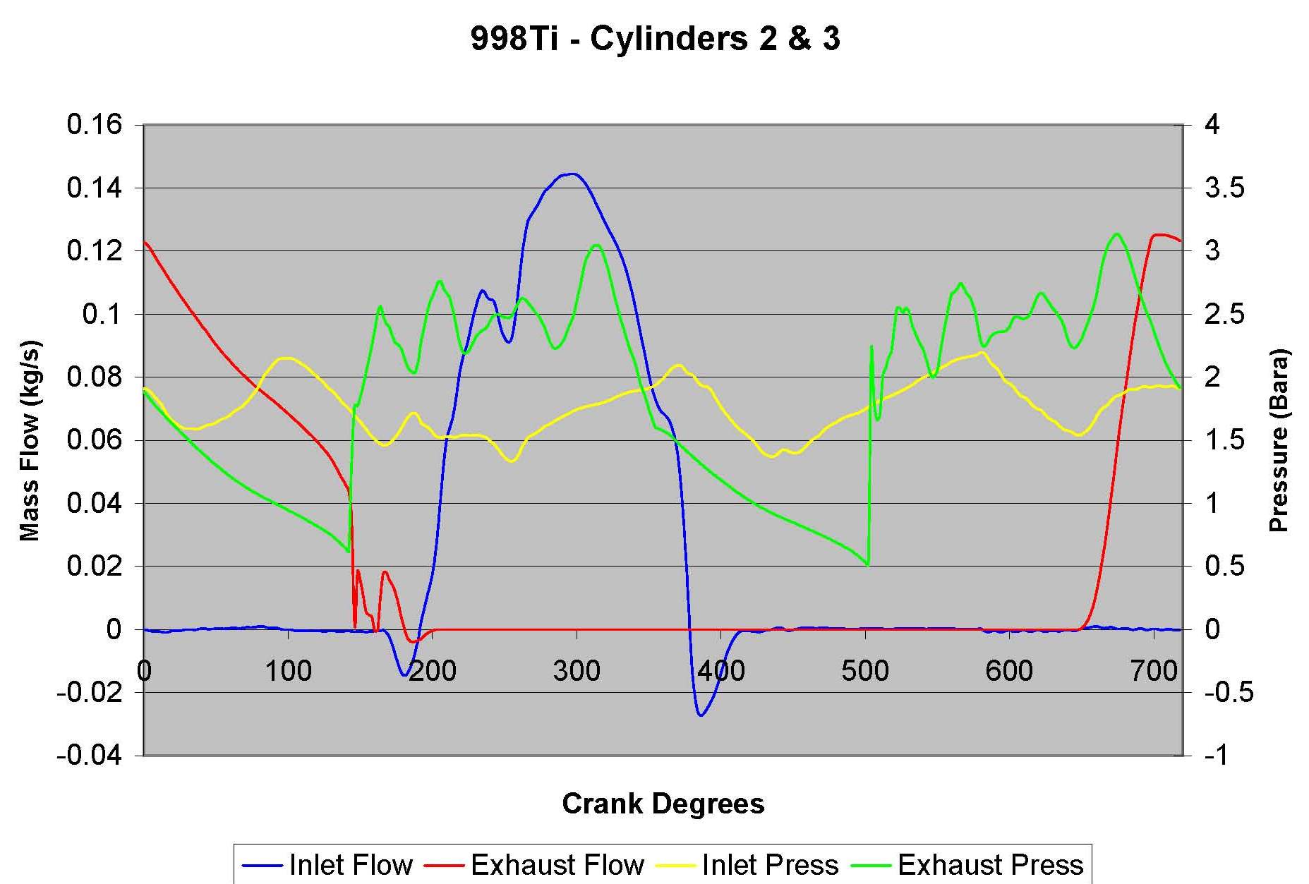
I assume that the red trace is the inner cylinder inlet flow, in which case you can see the charge robbing when the flow goes negative.
Saul Bellow - "A great deal of intelligence can be invested in ignorance when the need for illusion is deep."
|
||||||
|
510 Posts Member #: 1592 Smart Guy! mainland europe near ze germans |
16th Oct, 2014 at 09:41:03pm
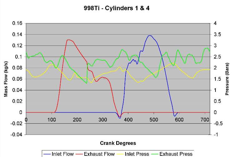
yep 3 is cylinder three and 4 is cylinder four .
Edited by Sir Yun on 16th Oct, 2014. That sir, is not rust, it is the progressive mass reduction system
|
||||||
|
8604 Posts Member #: 573 Formerly Axel Podland |
17th Oct, 2014 at 07:32:32am
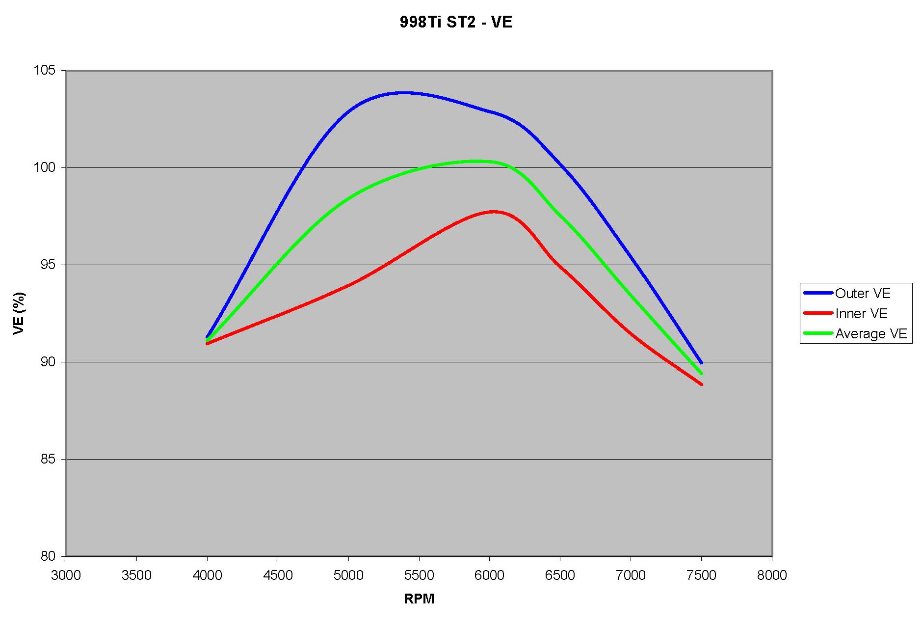
We are only looking at a few percent difference in VE, not a "really big chunk".
Edited by Paul S on 17th Oct, 2014. Saul Bellow - "A great deal of intelligence can be invested in ignorance when the need for illusion is deep."
|
||||||
 774 Posts Member #: 6724 Post Whore Wootton Bassett |
17th Oct, 2014 at 11:44:37am
I used it for my fianl year uni project. I looked at inlet manifold and drivetrain optimisation for our formula student car.
On 16th Oct, 2014 jakejakejake1 said:
I have recently started using Ricardo WAVE, but I'm not too well versed in it yet. But it would be nice to get a nice 1D engine model up and running for the A series engine. Does anyone on here use WAVE? |
||||||
|
293 Posts Member #: 10010 Senior Member Northants |
17th Oct, 2014 at 08:06:08pm
On 17th Oct, 2014 dan187 said:
I used it for my fianl year uni project. I looked at inlet manifold and drivetrain optimisation for our formula student car. I want to make an A-series model but never got round to it. On 16th Oct, 2014 jakejakejake1 said: I have recently started using Ricardo WAVE, but I'm not too well versed in it yet. But it would be nice to get a nice 1D engine model up and running for the A series engine. Does anyone on here use WAVE? I am starting to do something similar but I'm looking into turbocharger and exhaust optimisation for a Formula Student car, but I'm not too handy with WAVE yet, and our engine model isn't giving us very good results as a result of some iffy heat transfer assumptions I believe. I might try and start on an A series model and compare to real word results to see if its anywhere close to reality. |
||||||
|
510 Posts Member #: 1592 Smart Guy! mainland europe near ze germans |
19th Oct, 2014 at 01:19:27pm
On 17th Oct, 2014 Paul S said:
We are only looking at a few percent difference in VE, not a "really big chunk". You need to consider the area under the curve. The outer cylinder is filling for longer as well as getting a helping hand at the start of the valve opening. I know but I was referring to your charge robbing graph above where a big chunk is ''missing'' from the second mass flow trace. The small negative section of the inner cylinder does not seem to explain this. ( not trying to be contrarian, i'm just trying to understand :) I counted the pixels under the curve and the inner gets about 123k vs outer 126k pixels. So the total mass flow is pretty much the same but the time when is takes place is different. A big deal for port injection but when you feed it a fixed AF mix it does matter a bit less ? 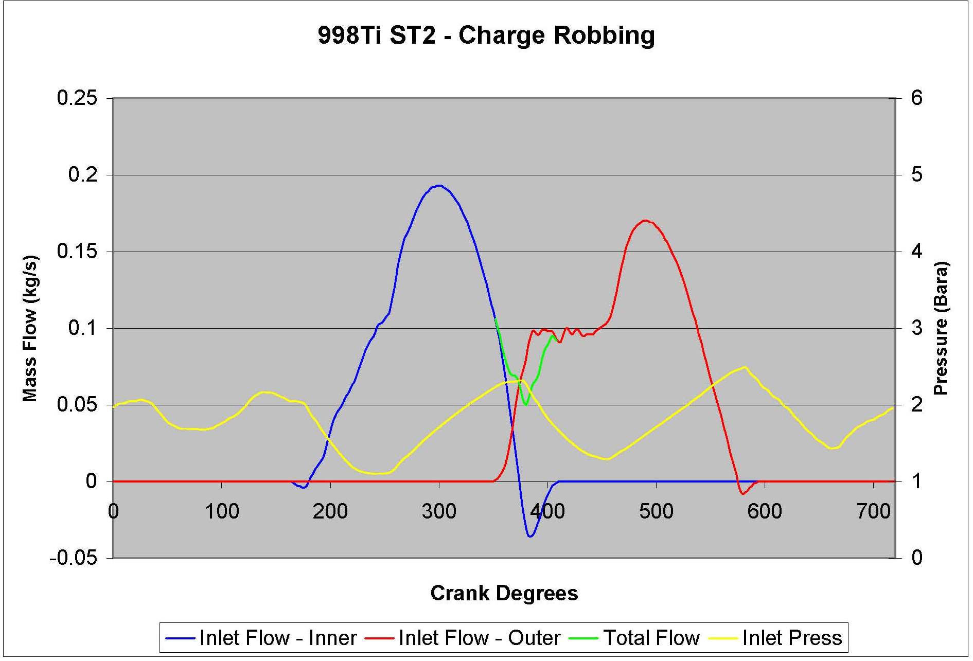
On 17th Oct, 2014 Paul S said:
EDIT: I'm not sure what the black line shows, but I can see that you may be looking at the difference between it and the cylinder traces. I guess that the black line is the mass flow at the inlet to the carb? What you are seeing is some compression of the flow within the port. The black line is mass flow at the headface, two other traces are at the border of the SSR. I interpreted it as slight amount of compression as well. My thinking is, that whatever total mass flow you have into the head can never be exceeded by the combined mass flow of the two cylinders (the other way around i.e. more mass flow in than out would indicate compression effects). I'm will be trying to replicate the dyno figures of a mini7 engine from NZ ( isn't the internet great !  ) )
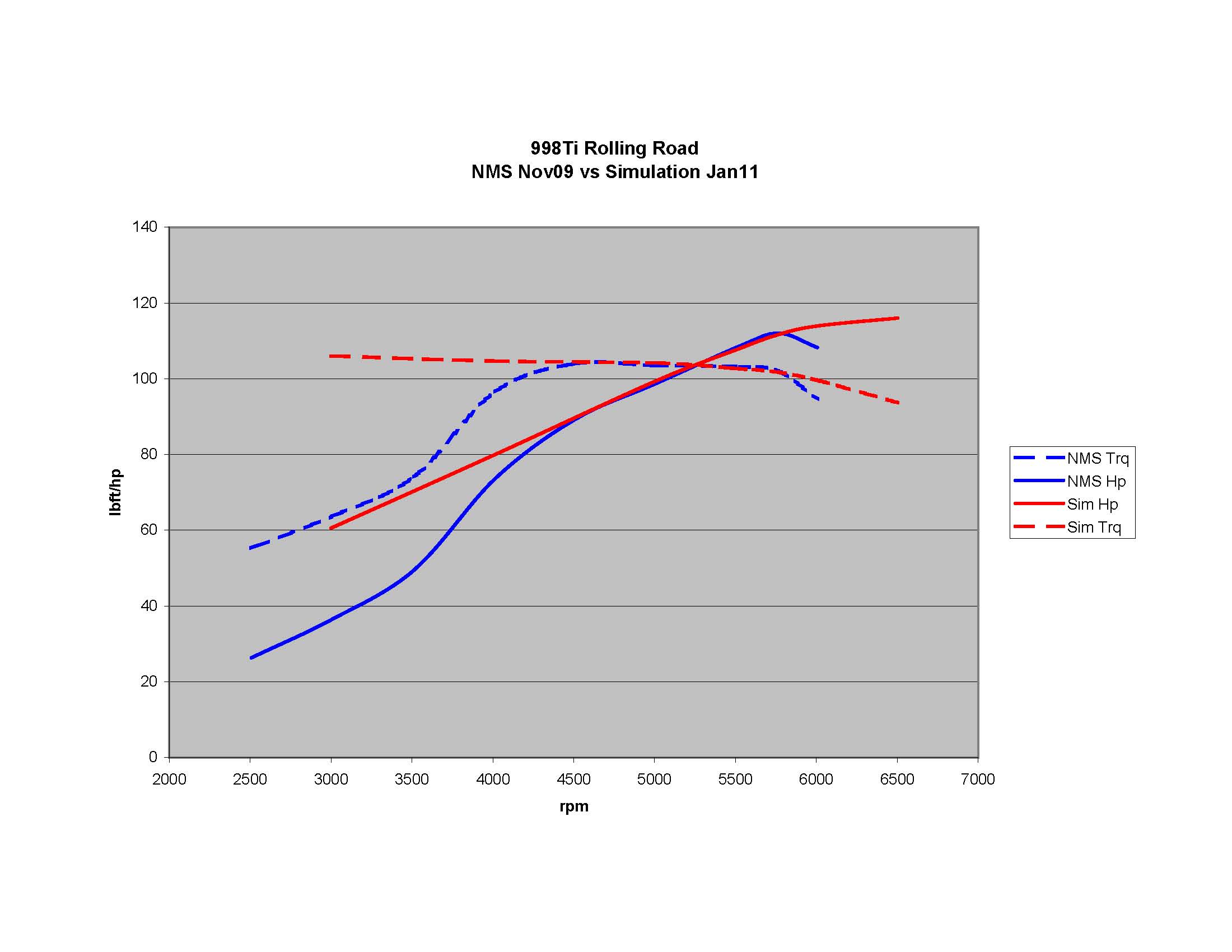
I have just received dyno figures, head flow( stock by the looks of it) and S 96 cam file and the rest is pretty much stock. will be interesting if that works Edited by Sir Yun on 19th Oct, 2014. That sir, is not rust, it is the progressive mass reduction system
|
||||||
|
8604 Posts Member #: 573 Formerly Axel Podland |
19th Oct, 2014 at 01:35:49pm
I can't see anything missing. Do you mean the part when it flattens out? Saul Bellow - "A great deal of intelligence can be invested in ignorance when the need for illusion is deep."
|
||||||
|
510 Posts Member #: 1592 Smart Guy! mainland europe near ze germans |
19th Oct, 2014 at 01:40:42pm
yeah I mean that bit. That sir, is not rust, it is the progressive mass reduction system
|
||||||
|
8604 Posts Member #: 573 Formerly Axel Podland |
19th Oct, 2014 at 01:48:44pm
Charge robbing can only occur when both inlet valves on the port are open, so on my trace that is where the green line is visible.
Saul Bellow - "A great deal of intelligence can be invested in ignorance when the need for illusion is deep."
|
||||||
|
8604 Posts Member #: 573 Formerly Axel Podland |
19th Oct, 2014 at 02:21:41pm
Just found the latest data for the simulation. It has been developed since that plot, but the shape is much the same.
Edited by Paul S on 19th Oct, 2014. Saul Bellow - "A great deal of intelligence can be invested in ignorance when the need for illusion is deep."
|
||||||
|
109 Posts Member #: 10368 Advanced Member Australia |
20th Oct, 2014 at 12:55:16am
Way below the intellectual level of the previous posts, but in some other engines it is quite common to have different rocker ratios for inlet and exhaust, so has anyone modelled larger diameter exhaust on two cylinders or someother such workaround to get the inner and outers to behave more similarly? |
||||||
|
510 Posts Member #: 1592 Smart Guy! mainland europe near ze germans |
20th Oct, 2014 at 09:31:41am
I haven't yet as i first want to know if the sims can match data on a relatively simple case. I might try to model a generic 7 port just to have a look at the siamese exhaust behaviour in isolation. And model 10 cm stubs (RR merlin style) as they are quite neutral with regards to tuning for the 5 porter
Edited by Sir Yun on 20th Oct, 2014. That sir, is not rust, it is the progressive mass reduction system
|
||||||
|
8604 Posts Member #: 573 Formerly Axel Podland |
20th Oct, 2014 at 10:24:33am
On 20th Oct, 2014 Sir Yun said:
And model 10 cm stubs (RR merlin style) as they are quite neutral with regards to tuning for the 5 porter Where did you get that idea? There's enough data in the plots above to show the impact of a short exhaust manifold runner 
Still interested in what your simulation chucks out. Be interesting to compare it with 50cm stubs. Saul Bellow - "A great deal of intelligence can be invested in ignorance when the need for illusion is deep."
|
||||||
|
510 Posts Member #: 1592 Smart Guy! mainland europe near ze germans |
20th Oct, 2014 at 08:22:49pm
I read it in Blairs book somewhere . .
That sir, is not rust, it is the progressive mass reduction system
|
||||||
|
8604 Posts Member #: 573 Formerly Axel Podland |
20th Oct, 2014 at 08:34:08pm
You may be right about the 10cm runners, particularly on the inner cylinders. Impractical though.
Saul Bellow - "A great deal of intelligence can be invested in ignorance when the need for illusion is deep."
|
||||||
|
510 Posts Member #: 1592 Smart Guy! mainland europe near ze germans |
21st Oct, 2014 at 06:38:22pm
found where I read it. page 653..used as a tuning neutral exhaust for the examining the fundamentals of intake tuning.
That sir, is not rust, it is the progressive mass reduction system
|
||||||
|
8604 Posts Member #: 573 Formerly Axel Podland |
22nd Oct, 2014 at 08:33:52am
Sounds like a good starting point.
Saul Bellow - "A great deal of intelligence can be invested in ignorance when the need for illusion is deep."
|
||||||
|
510 Posts Member #: 1592 Smart Guy! mainland europe near ze germans |
22nd Oct, 2014 at 09:59:30am
I have some (engine ? not shure anymore) dyno data for the seven. The s96 cam data should be functional .
Edited by Sir Yun on 23rd Oct, 2014. That sir, is not rust, it is the progressive mass reduction system
|
||||||
|
510 Posts Member #: 1592 Smart Guy! mainland europe near ze germans |
23rd Oct, 2014 at 08:46:48am
Well, first tries are not matching the dyno . general shape is pretty decent but i make way too much power. adjusted the dcr to 8 which helps a lot to get it in the neighbourhood (10:1 static CR with a kelford f11 cam). Have to revisit the burn models and fmep if they need tweaking to see if i can get it nearer . That sir, is not rust, it is the progressive mass reduction system
|
||||||
|
8604 Posts Member #: 573 Formerly Axel Podland |
23rd Oct, 2014 at 10:28:55am
My software gives gross crank power, so you need to account for some losses.
Saul Bellow - "A great deal of intelligence can be invested in ignorance when the need for illusion is deep."
|
||||||
|
510 Posts Member #: 1592 Smart Guy! mainland europe near ze germans |
23rd Oct, 2014 at 05:02:52pm
You are right. turns out you can use a more extensive friction loss model where you specify engine main parameters, oil type, valve train type, bearing sizes and diameters and some more stuff. Then it calculates the losses for the components vs rpm.
Edited by Sir Yun on 23rd Oct, 2014. That sir, is not rust, it is the progressive mass reduction system
|
||||||
| Home > Technical Chat > A Series simulation thread. | |||||||
|
|||||||


| Page: |